
Detection method and laser radar of Raman-Mie scattering laser atmospheric signal

A detection method, laser technology, applied in the direction of measuring devices, using re-radiation, climate sustainability, etc., can solve the problems of large volume, weak scattered echo signal, difficult to move and transport, etc.

Inactive Publication Date: 2005-08-24
ANHUI INST OF OPTICS & FINE MECHANICS - CHINESE ACAD OF SCI
View PDF0 Cites 39 Cited by
  • Summary
  • Abstract
  • Description
  • Claims
  • Application Information

AI Technical Summary

Problems solved by technology

[0004] At present, lidar systems for detecting tropospheric atmospheric aerosols and water vapor generally have the following four deficiencies: First, in view of the increase of lidar detection functions, the radar system will be more complicated, larger in size, heavier in weight, and difficult to move and transport , which limits its application range; secondly, the detection height is limited, and the detection of atmospheric aerosols is mostly confined to the boundary layer below 5-6km, and water vapor has very little content in the atmosphere, and at the same time it is related to The Raman scattering echo signal generated by the laser is very weak, and its measurement height is only below 5km
[0010] Domestically, the L625 multifunctional lidar built by the Atmospheric Optics Center of Anhui Institute of Optics and Mechanics, Chinese Academy of Sciences was mainly used in 1995. This radar added a Raman channel for measuring water vapor in 1999, but due to the limitation of the radar itself, it can only conduct 1 ~5km water vapor measurement, and only limited to night observations

Method used


Image

  • Detection method and laser radar of Raman-Mie scattering laser atmospheric signal
  • Detection method and laser radar of Raman-Mie scattering laser atmospheric signal
  • Detection method and laser radar of Raman-Mie scattering laser atmospheric signal

Examples


Embodiment Construction

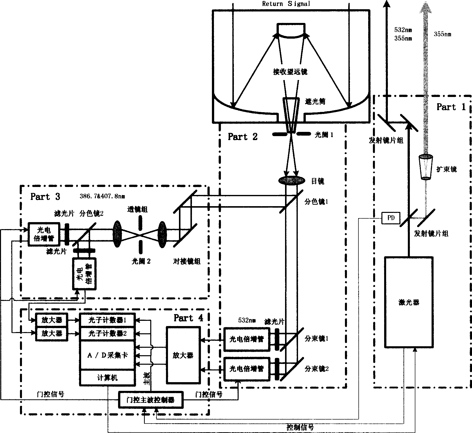
[0039] The schematic diagram of the mechanism of the vehicle-mounted Raman-Mie scattering laser radar system of the present invention is as follows figure 1 shown.

[0040] Raman-Mie scattering lidar, which consists of four parts:

[0041] (1) Emitting unit: use laser as the laser emission source, install a dichroic mirror at the front end of the laser, the front end of the dichroic mirror is equipped with an emitting lens group composed of a total reflection mirror, and the dichroic mirror is completely transparent to the 532nm light emitted by the laser , 355nm light is 15% transparent, 85% of the 355nm light is reflected to the total reflection mirror, and then shoots to the sky through the 355nm wavelength beam expander. parallel;

[0042] (2) Radar receiving and follow-up optical unit: including a Cassegrain type telescope that is movable and capable of pitching movement, and the rear end of the Cassegrain type telescope is sequentially installed with a light-shielding ...


PUM


Abstract

This invention is a detecting of Roman-Mie dispersion laser atmosphere signal and laser radar. It sets up the radar with the output of double-frequency 532nm and triple-frequency 355nm, launches the 532nm, 15% of the 35nm to the sky and 85% of the 355nm after diffusion, and the two optical paths parallel with the optical path of the receiving telescope, and simultaneously carry out the pitching motion with the receiving telescope; the receiving telescope backward dispersing light, the backward light gets into the telescope, then passes the glare tube, the adjusting field view stop and ocular glass, and the dichroic mirror process, and divides the 407nm, the 386nm and the 532nm scattered light into three beams, and the 532nm scattered light is divided into 15% and 85% beams, and the four beams are respectively received by the multiplier phototube, magnified by the magnifier and collect and process the data. It can detect the level visibility of the atmosphere, the aerosol of the whole troposphere and the vertical outline of winding cloud light eliminating system and the water and air mixture ratio from the ground to the lower part of the troposphere. The detecting error of the level visibility is 15%, the errors of the aerosol light eliminating modulus and the vertical outline of the water and air mixture are 20%.

Description

technical field [0001] The invention relates to a method for detecting atmospheric horizontal visibility, atmospheric aerosol and water vapor spatial distribution and a vehicle-mounted laser radar. technical background [0002] Lidar uses laser light as a light source to remotely sense the atmosphere by detecting the radiation signal of the interaction between the laser and the atmosphere. The interaction between the laser and the atmosphere produces a radiation signal containing information about atmospheric gas molecules and aerosol particles, and the information about gas molecules and aerosol particles can be obtained from it by using a suitable inversion method combined with radar equations. [0003] Lidar is the product of the combination of traditional radar detection technology and modern laser technology. In the second year after the advent of the laser, that is, in 1961, scientists proposed the idea of ​​laser radar and carried out research work. For more than 40 ...

Claims


Application Information

Patent Timeline
IPC IPC(8): G01S17/95
CPCY02A90/10
Inventor 谢晨波戚福弟范爱媛岳古明徐吉胜兰举生曹京平江庆伍袁松尹君周军
Owner ANHUI INST OF OPTICS & FINE MECHANICS - CHINESE ACAD OF SCI
Learn More