
Baffle device for valve body upper cover machining line

A technology of baffle device and valve body upper cover, which is applied in the direction of positioning device, metal processing equipment, metal processing machinery parts, etc., can solve the problems of low processing efficiency, inconvenient operation, inaccurate positioning, etc., and achieve easy operation, The effect of simple structure

Inactive Publication Date: 2016-10-26
苏州市吴中区木渎晓云模具加工厂
View PDF6 Cites 0 Cited by
  • Summary
  • Abstract
  • Description
  • Claims
  • Application Information

AI Technical Summary

Problems solved by technology

[0002] During the processing of the upper cover of the valve body, a baffle device is required to position the upper cover of the valve body when it is sent to the next processing place. The existing baffle device has a complex structure, is not easy to operate, and is not positioned accurately. , so that the processing efficiency is not high

Method used


Image

  • Baffle device for valve body upper cover machining line

Examples


Embodiment Construction

[0007] The preferred embodiments of the present invention will be described in detail below in conjunction with the accompanying drawings, so that the advantages and features of the invention can be more easily understood by those skilled in the art, so as to define the protection scope of the present invention more clearly.

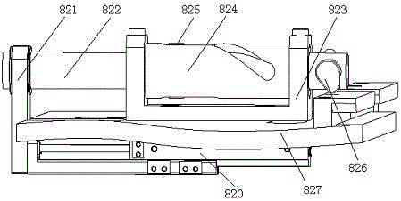
[0008] see figure 1 , the embodiment of the present invention includes:

[0009] A baffle device of a valve body upper cover processing line, the baffle device of the valve body upper cover processing line includes a first mounting plate 827, a sliding table cylinder 820 is installed on the lower end surface of the first mounting plate 827, and the sliding table cylinder 820 A sliding table cylinder connecting plate 821 perpendicular to it is installed on the piston rod of the sliding table cylinder, a clamp seat stop post 822 is inserted on the slide table cylinder connection plate 821, and a fixture seat stop post fixing seat 823 is installed on the up...


PUM


Abstract

The invention discloses a baffle device for a valve body upper cover machining line. The baffle device for the valve body upper cover machining line comprises a first installation plate. A sliding table air cylinder is installed on the lower end face of the first installation plate. A sliding table air cylinder connecting plate perpendicular to a piston rod of the sliding table air cylinder is installed on the piston rod of the sliding table air cylinder. A clamp seat blocking pillar is inserted in the sliding table air cylinder connecting plate. A clamp seat blocking pillar fixing seat is installed on the upper plane of the first installation plate. A clamp seat blocking pillar protection shell is installed on the clamp seat blocking pillar fixing seat. The clamp seat blocking pillar penetrates the clamp seat blocking pillar fixing seat and the clamp seat blocking pillar protection shell. A spiral sliding groove is formed in the clamp seat blocking pillar protection shell. A limiting pin is arranged at the position, located between the two ends of the clamp seat blocking pillar fixing seat, on the clamp seat blocking pillar. The limiting pin can slide in the sliding groove in the clamp seat blocking pillar protection shell, and a blocking pillar adjusting device is arranged at the end of the clamp seat blocking pillar. By means of the above manner, a valve body upper cover can be blocked accurately through the coordination work of the air cylinder, a baffle and a pin shaft.

Description

technical field [0001] The invention relates to the field of mechanical automation, in particular to a baffle device of a valve body upper cover processing line. Background technique [0002] During the processing of the upper cover of the valve body, a baffle device is required to position the upper cover of the valve body when it is sent to the next processing place. The existing baffle device has a complex structure, is not easy to operate, and is not positioned accurately. , so that the processing efficiency is not high. Contents of the invention [0003] The technical problem mainly solved by the present invention is to provide a baffle plate device of a valve body upper cover processing line with simple structure and easy operation. [0004] In order to solve the above technical problems, a technical solution adopted by the present invention is to provide a baffle device of a valve body upper cover processing line, the baffle device of the valve body upper cover pro...

Claims


Application Information

Patent Timeline
Patent Type & Authority Applications(China)
IPC IPC(8): B23Q3/18
CPCB23Q3/18
Inventor 褚晓云
Owner 苏州市吴中区木渎晓云模具加工厂
Learn More