A pivoting arm structure with wire harness passing through the middle

A technology of rotating arm and threading, which is applied in the direction of handrails, etc., which can solve the problems of easy damage of wire harness, unsightly appearance, inconvenient use of electronic screen, etc., and achieve the effect of satisfying use and avoiding poor aesthetics

Active Publication Date: 2018-03-06
YANFENG ADIENT SEATING CO LTD
View PDF5 Cites 0 Cited by
  • Summary
  • Abstract
  • Description
  • Claims
  • Application Information

AI Technical Summary

Problems solved by technology

However, because the existing arm structure does not have accommodating grooves for accommodating wire harnesses, when electronic screens and the like are arranged on the arm structure, the wire harnesses are often exposed, which is not only unsightly, but also easily damaged
In addition, the existing rotating arm structure usually cannot rotate in two directions and stop at the required position, which also leads to inconvenience in the use of electronic screens, etc.

Method used


Image

  • A pivoting arm structure with wire harness passing through the middle
  • A pivoting arm structure with wire harness passing through the middle
  • A pivoting arm structure with wire harness passing through the middle

Examples


Embodiment Construction

[0032] Below in conjunction with the drawings, preferred embodiments of the present invention are given and described in detail.

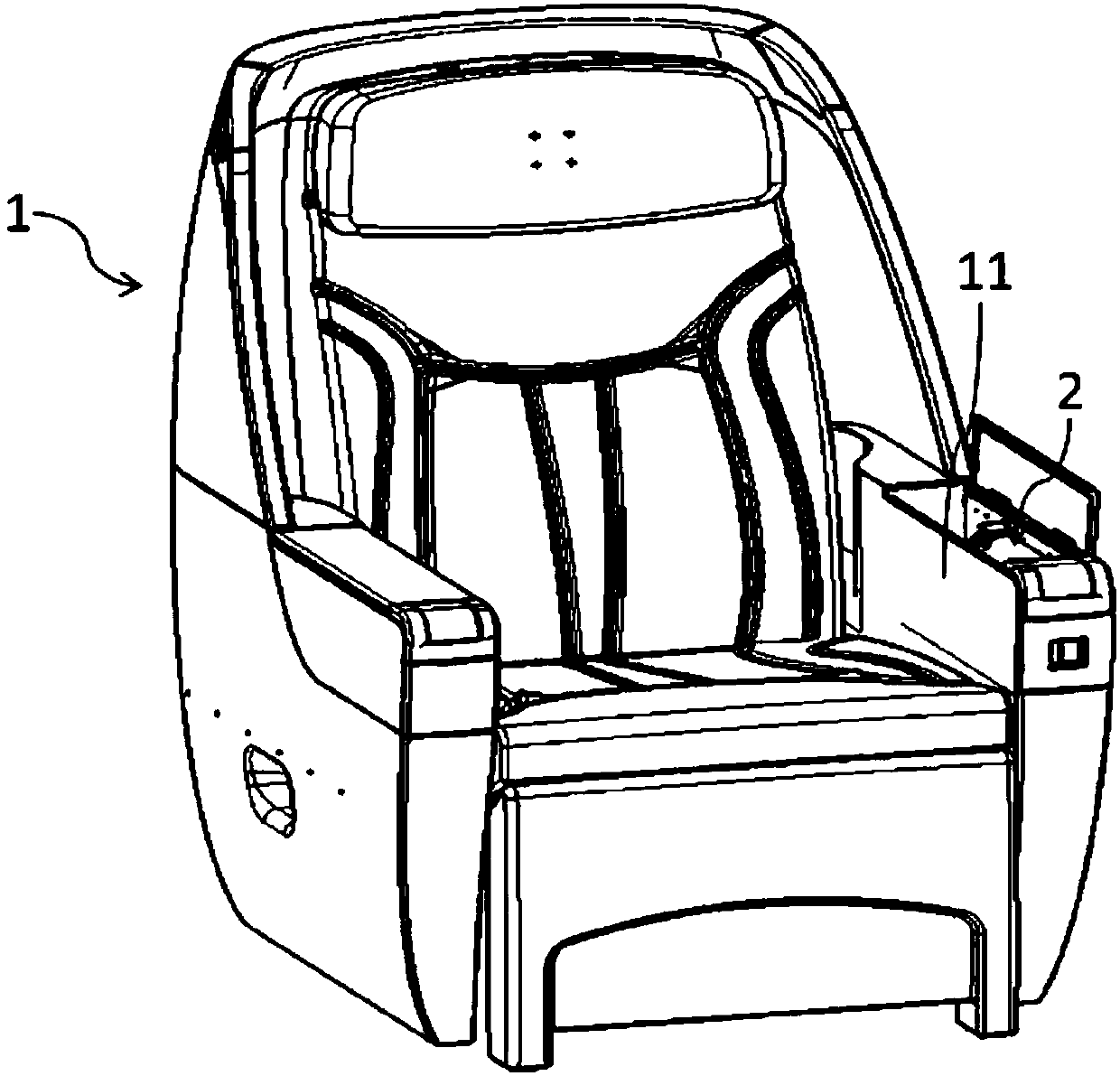
[0033] figure 1 Shown is a vehicle seat 1 in which a pivot arm structure 2 according to the invention is installed in the left armrest 11 .

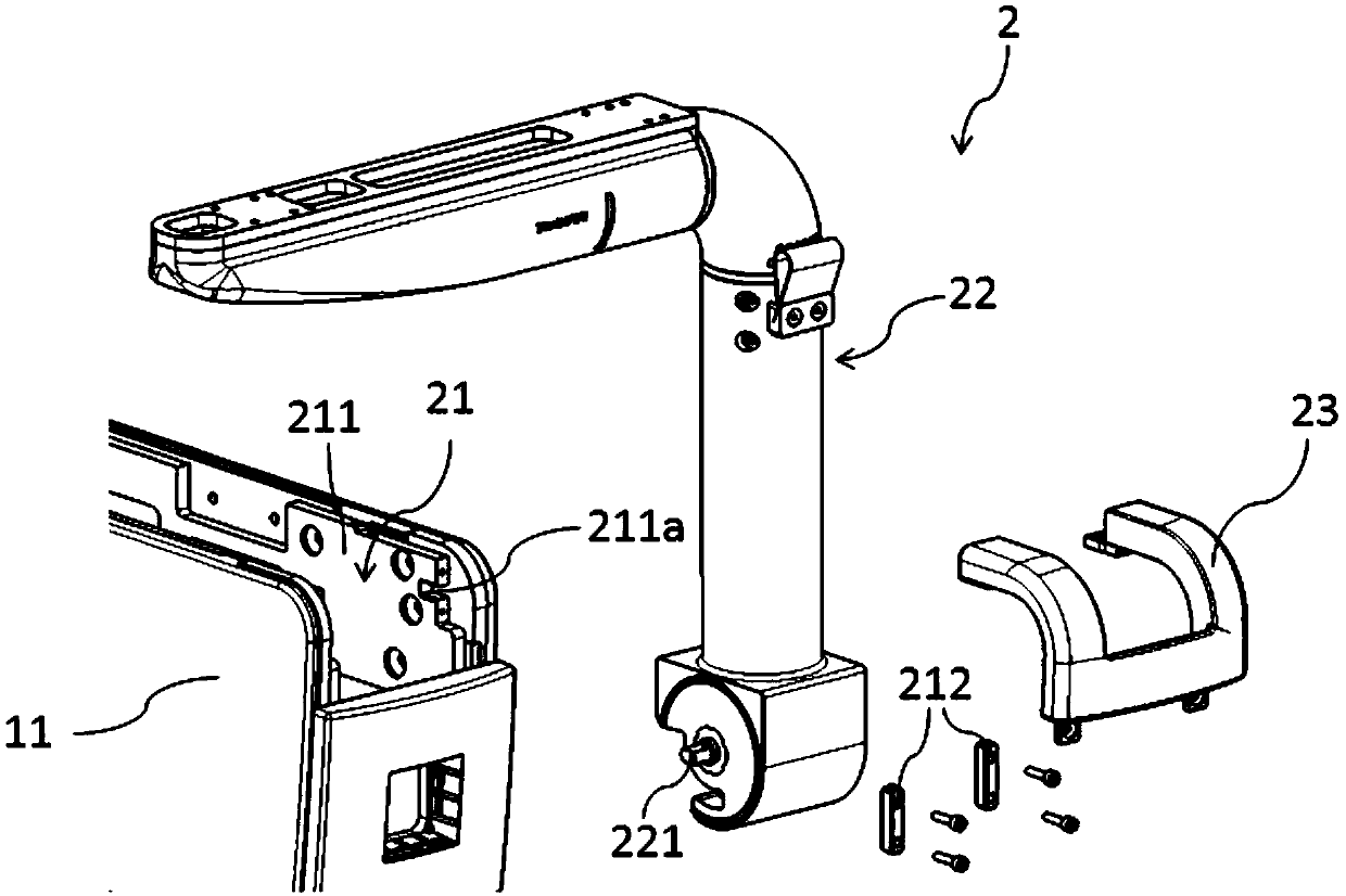
[0034] figure 2 yes figure 1 A partial schematic diagram of the left armrest 11 and the pivoting arm structure 2 of the present invention. Wherein, the left armrest 11 includes two opposite side plates, defining a space for accommodating the rotating arm structure 2 therebetween. The rotating arm structure 2 includes a fixing frame 21 , a rotating arm main body 22 and a decorative cover 23 . Wherein, the fixing frame 21 includes two opposite fixing plates 211 (only one side fixing plate is indicated in the figure), which are respectively fixed on the inner sides of the two side plates of the left armrest 11 . The front end of the side fixing plate 211 has a rectangular groove 211a. The fixing frame 21 ...


PUM


Abstract

The invention relates to a rotating arm structure with a wire harness penetrating through the middle of the rotating arm structure. The rotating arm structure comprises a fixed frame and a rotating arm main body, wherein the fixed arm is provided with two side fixed plates which are fixed into a seat armrest and arranged oppositely, and the front end of each side fixed plate is provided with a groove; the rotating arm main body is clamped between the two side fixed plates and provided with a rotating shaft, a transverse rotating arm assembly, an elbow assembly and a vertical rotating arm assembly; the two ends of the rotating shaft are fixed into the grooves; the vertical rotating ram assembly is arranged on the rotating shaft in a sleeving mode and can rotate around the rotating shaft; one end of the elbow assembly is connected to the end, away from the rotating shaft, of the vertical rotating arm assembly and can rotate around in the vertical direction; the transverse rotating arm assembly is connected to the other end of the elbow assembly and can rotate in the horizontal direction; and the transverse rotating arm assembly, the elbow assembly and the vertical rotating arm assembly are all internally provided with hollow cavities for accommodating the wire harness. According to the rotating arm structure with the wire harness penetrating through the middle of the rotating arm structure, the wire harness can penetrate through the transverse rotating arm assembly, the elbow assembly and the vertical rotating arm assembly in sequence, so that the wire harness is accommodated in the rotating arm structure, and the problems of the poor aesthetic property and breakage caused by wire harness exposure are solved.

Description

technical field [0001] The invention relates to a rotating arm structure installed on a seat, and more particularly relates to a rotating arm structure through which a harness is threaded in the middle. Background technique [0002] It is a prior art to arrange the rotating arm structure on the seat, especially the installation of the rotating arm structure on the vehicle seat is more and more widely used. However, because the existing rotating arm structure does not have accommodating grooves for accommodating wire harnesses, when electronic screens and the like are arranged on the rotating arm structure, the wire harnesses are often exposed, which is not only unsightly, but also easily damaged. In addition, the existing rotating arm structure usually cannot rotate in two directions and stop at a desired position, which also causes inconvenience in the use of electronic screens and the like. Contents of the invention [0003] In order to solve the above-mentioned problem...

Claims


Application Information

Patent Timeline
Patent Type & Authority Patents(China)
IPC IPC(8): B60N2/75
CPCB60N2/79
Inventor 张涛宋卿李侠
Owner YANFENG ADIENT SEATING CO LTD
Why Eureka
Try Eureka