Method for controlling light fixtures

A lighting and controlled technology, applied in vehicle components, signaling devices, optical signals, etc., can solve problems such as being unsuitable for personalization

Inactive Publication Date: 2018-12-28
DR ING H C F PORSCHE AG
View PDF6 Cites 0 Cited by
  • Summary
  • Abstract
  • Description
  • Claims
  • Application Information

AI Technical Summary

Problems solved by technology

[0005] Since known motor vehicles have the same functions in this respect, the relevant processing methods are not suitable for individual-specific or vehicle-specific or manufacturer-specific personalization

Method used


Image

  • Method for controlling light fixtures
  • Method for controlling light fixtures

Examples


Embodiment Construction

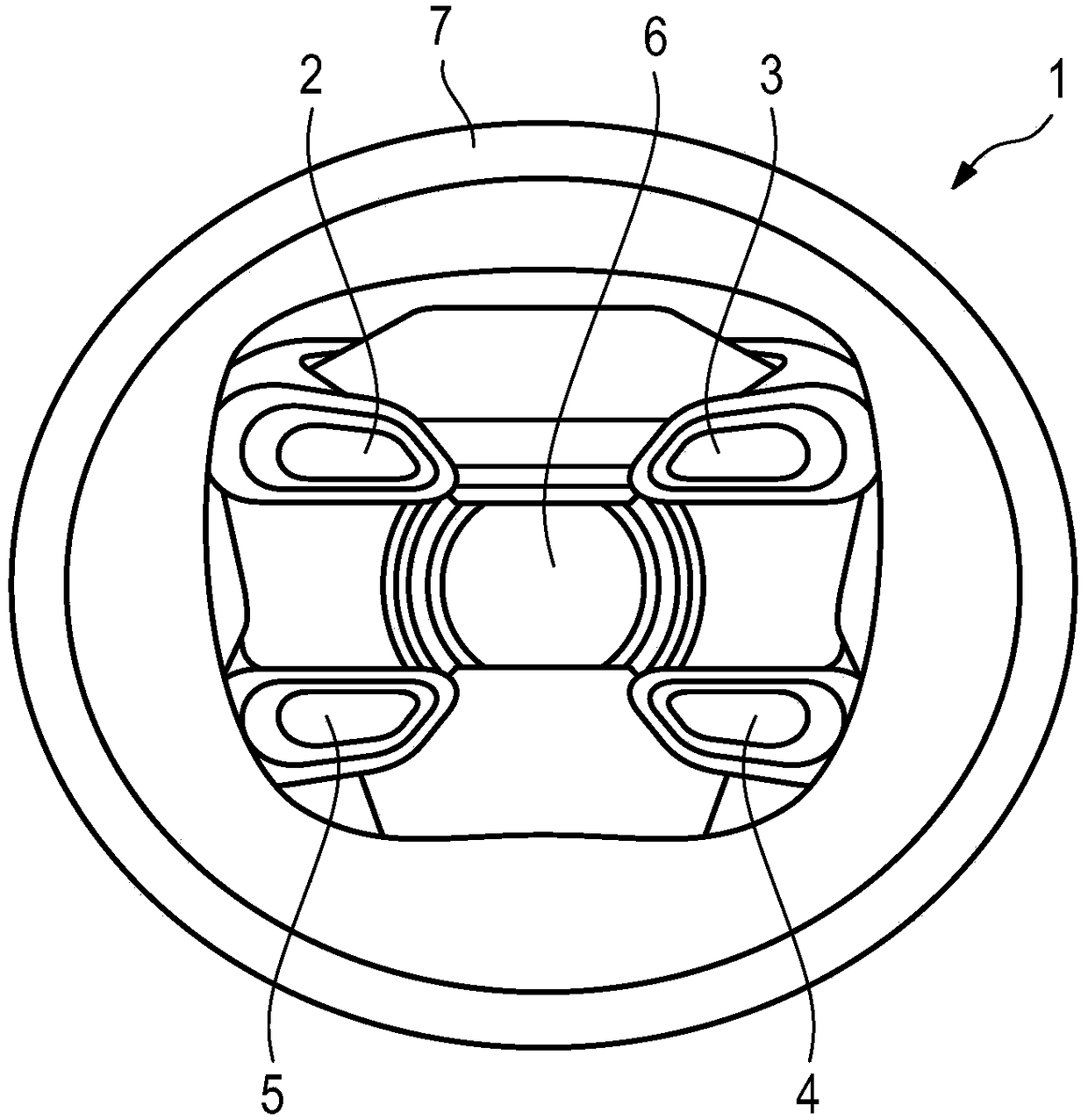
[0024] figure 1 A schematic diagram of a lamp 1 for a motor vehicle is shown, which is in figure 1 In the exemplary embodiment shown, it is formed as a headlight. Alternatively, the light fixture can also be formed as a rear light.

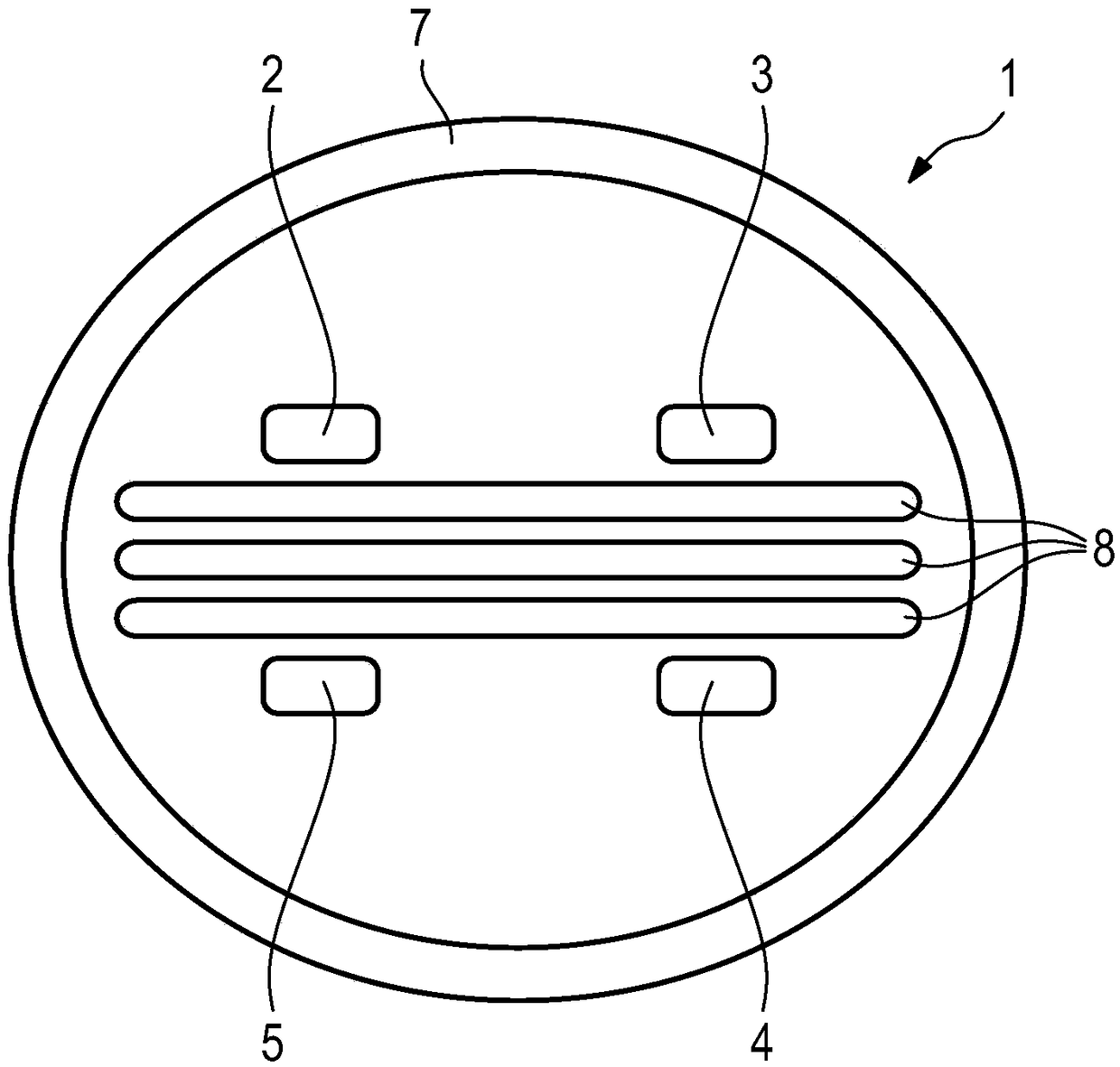
[0025] As headlights, these lamps have four luminous surfaces 2 , 3 , 4 , 5 as daytime running lights or, where appropriate, also as luminous surfaces for dipped beams. These light-emitting surfaces are arranged at the corners of rectangles or polygons, wherein the light-emitting surfaces themselves are not rectangular, but arranged flat in trapezoidal or drop-shaped shapes.

[0026] The main light module 6 for low beam and / or high beam is arranged in the central region of the luminaire 1 . Here, the main light module 6 is formed approximately as a flat, barrel-shaped element. The upper and lower parts of the element are formed flat and both sides are convex. In this case, the corners of the main light module 6 lie approximately on the inters...


PUM


Abstract

Method for controlling a luminaire (1) of a motor vehicle having a plurality of luminous surfaces (2, 3, 4, 5, 6, 7), such as in particular headlights or rear lights of a motor vehicle, the luminous surfaces It consists of one lighting element or a plurality of lighting elements, wherein at least some of the light-emitting surfaces (2, 3, 4, 5, 6, 7) are controlled to light up in a preset pattern and / or It is then controlled to extinguish in a preset pattern to signal a predefined vehicle state.

Description

technical field [0001] The invention relates to a method for controlling a lamp of a motor vehicle, such as in particular a headlamp or a rear lamp. Background technique [0002] Luminaires of motor vehicles are used, for example, as rear lights to assume the functions of rear lights, brake lights and, where appropriate, flashing lights. As lamps for motor vehicles, headlights for the front of the motor vehicle are also known, by means of which headlights can produce daytime running lights, parking lights, dipped beams and / or high beams and, where appropriate, also There are other lamp types for the front area of ​​motor vehicles. [0003] In this case, these lamps are usually only used during driving operation, wherein in some vehicles the switching on and off of the lamps takes place directly with the ignition of the internal combustion engine switched on or off or, if appropriate, also after switching off the ignition An adjustable follow-up runtime (Nachlaufzeit) for a...

Claims


Application Information

Patent Timeline
Patent Type & Authority Patents(China)
IPC IPC(8): B60Q1/50
CPCB60Q1/543B60Q1/44B60Q2900/50
Inventor G·西斯尔
Owner DR ING H C F PORSCHE AG
Why Eureka
Try Eureka