
Contactless Inductive Charging Mouse Pad

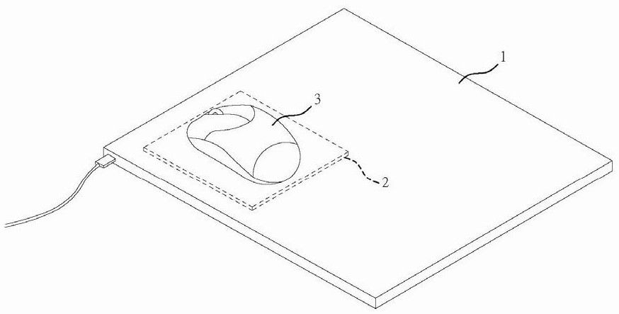
An inductive charging, non-contact technology, applied in the field of mouse pads, can solve the problems that the user cannot know whether the internal battery has enough power, the wireless charging mouse pad body loses its attractiveness, and the mouse pad body is empty.

Active Publication Date: 2021-08-31
CORSAIR MEMORY INC
View PDF5 Cites 0 Cited by
  • Summary
  • Abstract
  • Description
  • Claims
  • Application Information

AI Technical Summary

Problems solved by technology

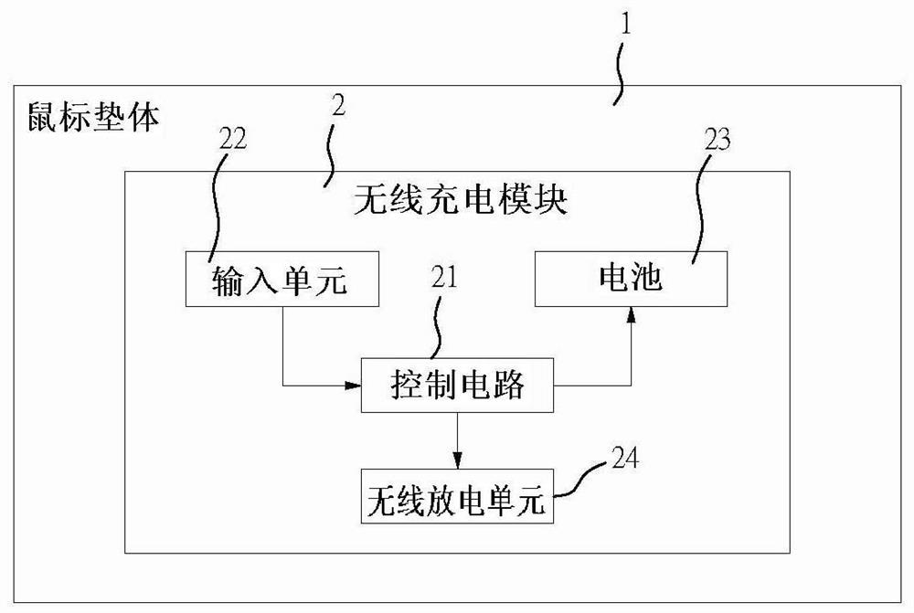
[0010] The known technology is to charge the battery with external power such as USB, and then transmit the power stored in the battery to the external mouse wirelessly, which will increase the cost and increase the volume of the mouse pad. Unfavorable to carry out
[0011] 2. Unable to understand the status of battery charging and external discharge:
[0012] Using USB to charge the lithium battery, the user cannot know whether the internal battery has sufficient power. This design method only moves the original battery inside the mouse to the outside of the mouse. When the mouse loses power, it still needs to reset the mouse first. After the internal battery of the pad is charged, the power stored in the battery can be used to supply power to the external mouse through wireless transmission. The user cannot understand the status of the battery charging and external discharge, and cannot solve the real problem.
[0013] 3. The mouse pad has no other additional functions:
[0014] Although the mouse pad body of the known technology has the control circuit to control the battery to discharge the wireless discharge unit, it does not have any additional functions. For users, purchasing a wireless charging mouse pad body will lose its appeal.

Method used


Image

  • Contactless Inductive Charging Mouse Pad
  • Contactless Inductive Charging Mouse Pad
  • Contactless Inductive Charging Mouse Pad

Examples


Embodiment Construction

[0044] The relevant characteristics and technical content of the present invention will be clearly presented in the following detailed description of two preferred embodiments with reference to the drawings. Before going into detail, it should be noted that similar components are designated with the same reference numerals.

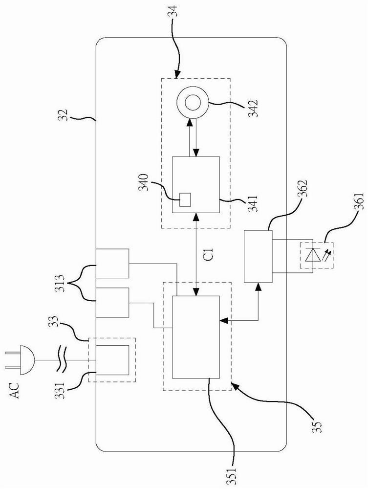
[0045] refer to image 3 , 4 As shown, it is the first preferred embodiment of the non-contact inductive charging mouse pad of the present invention. The mouse pad 3 is suitable for charging an external electric device 4, and includes a housing 31, a control substrate 32, a power supply The conversion unit 33 , a charging unit 34 , a processing unit 35 , and a display unit 36 ​​.

[0046]It should be noted here that the external power-consuming device 4 may be a wireless mouse, a smart phone or other 3C devices with wireless inductive charging. In the first preferred embodiment, the external power-consuming device 4 refers to What is a mouse with wirel...


PUM


Abstract

The invention relates to a non-contact inductive charging mouse pad, which is suitable for charging an external electric device, comprising a casing, a control substrate, a power conversion unit, a charging unit, a processing unit, and a display unit ; The casing defines an accommodating space around it, and there is a surface above which the external electrical equipment can be placed; the power conversion unit converts the external power supply for use by the control substrate; the charging unit is arranged on the control substrate , and includes an induction loop and an induction coil; the processing unit includes a microcontroller electrically connected to the charging unit; the display unit includes at least one light-emitting component arranged on the housing, and a light source driver, the micro The controller can control the light-emitting components to produce different light-emitting effects; the non-contact inductive charging mouse pad of the present invention can enable the user to wirelessly charge the external power-consuming equipment when using it, and can understand the charging of the external power-consuming equipment schedule.

Description

technical field [0001] The invention relates to a mouse pad, in particular to a non-contact induction charging mouse pad. Background technique [0002] The mouse is a very common and commonly used computer input device. It can locate the cursor on the current screen, and operate the screen elements at the position where the cursor passes through the button and the wheel device. With the progress of the times, the mouse has gradually evolved into a wireless input device to improve the convenience of operation and portability. [0003] Most of the current wireless mice use batteries as the power source, but they often face battery failure or no battery for backup, resulting in the wireless mouse not being able to operate in time. For workers who count against every second, or heavy users such as gaming players, etc. Accept that your mouse loses power at critical moments, and it takes time to replace batteries. [0004] In order to avoid the occurrence of the above situation,...

Claims


Application Information

Patent Timeline
Patent Type & Authority Patents(China)
IPC IPC(8): G06F3/039H02J50/10H02J50/80H02J7/00H02J7/02H05B33/08H05B44/00
CPCH02J7/0047H02J7/0063H02J7/02H02J50/10H02J50/80G06F3/0395H05B45/00
Inventor 林君彦李政霖
Owner CORSAIR MEMORY INC
Learn More