Collision energy absorption device and automobile

A collision energy absorption, automobile technology, applied in vehicle parts, transportation and packaging, substructure and other directions, can solve the problems of fast acceleration, low energy absorption, large collision intrusion, etc., to improve frontal collision and offset collision , Enhance collision energy absorption efficiency, and take into account the effect of collision lightweight

Active Publication Date: 2016-10-26
ZHEJIANG GEELY HLDG GRP CO LTD +1
View PDF13 Cites 6 Cited by
  • Summary
  • Abstract
  • Description
  • Claims
  • Application Information

AI Technical Summary

Problems solved by technology

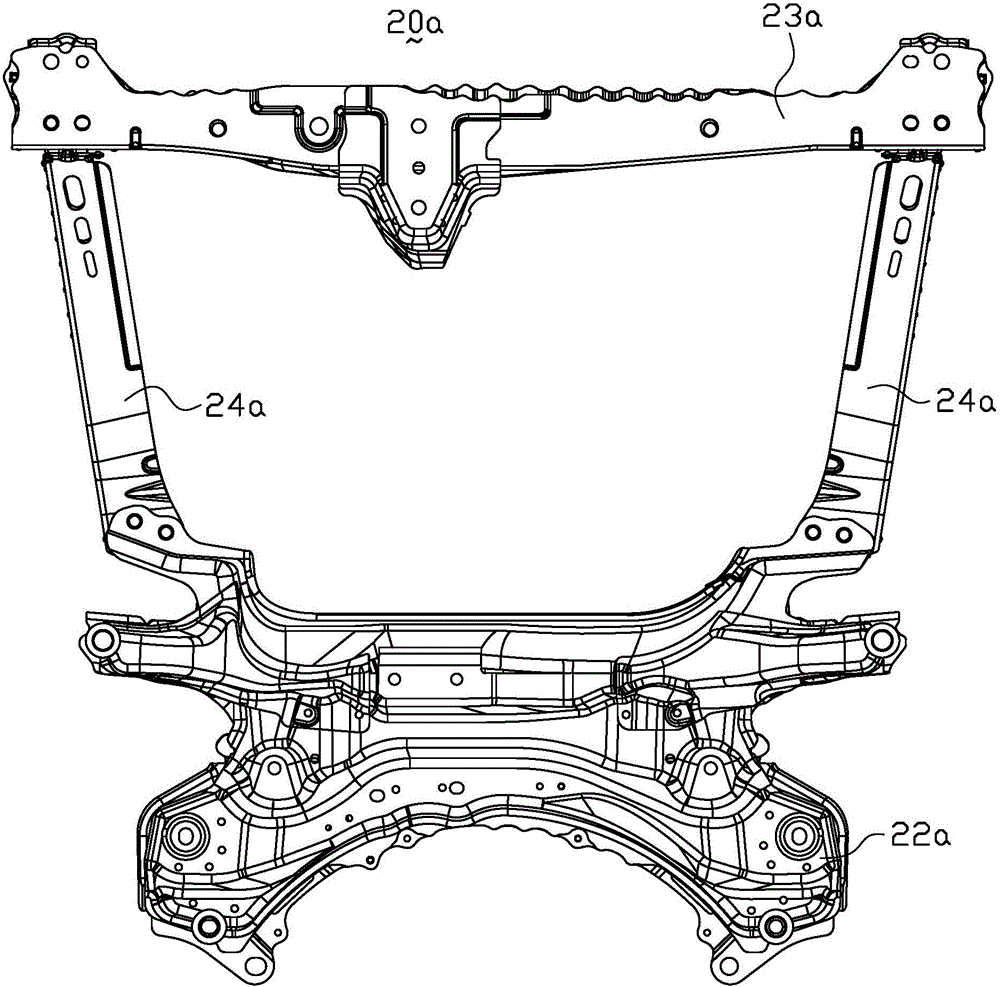
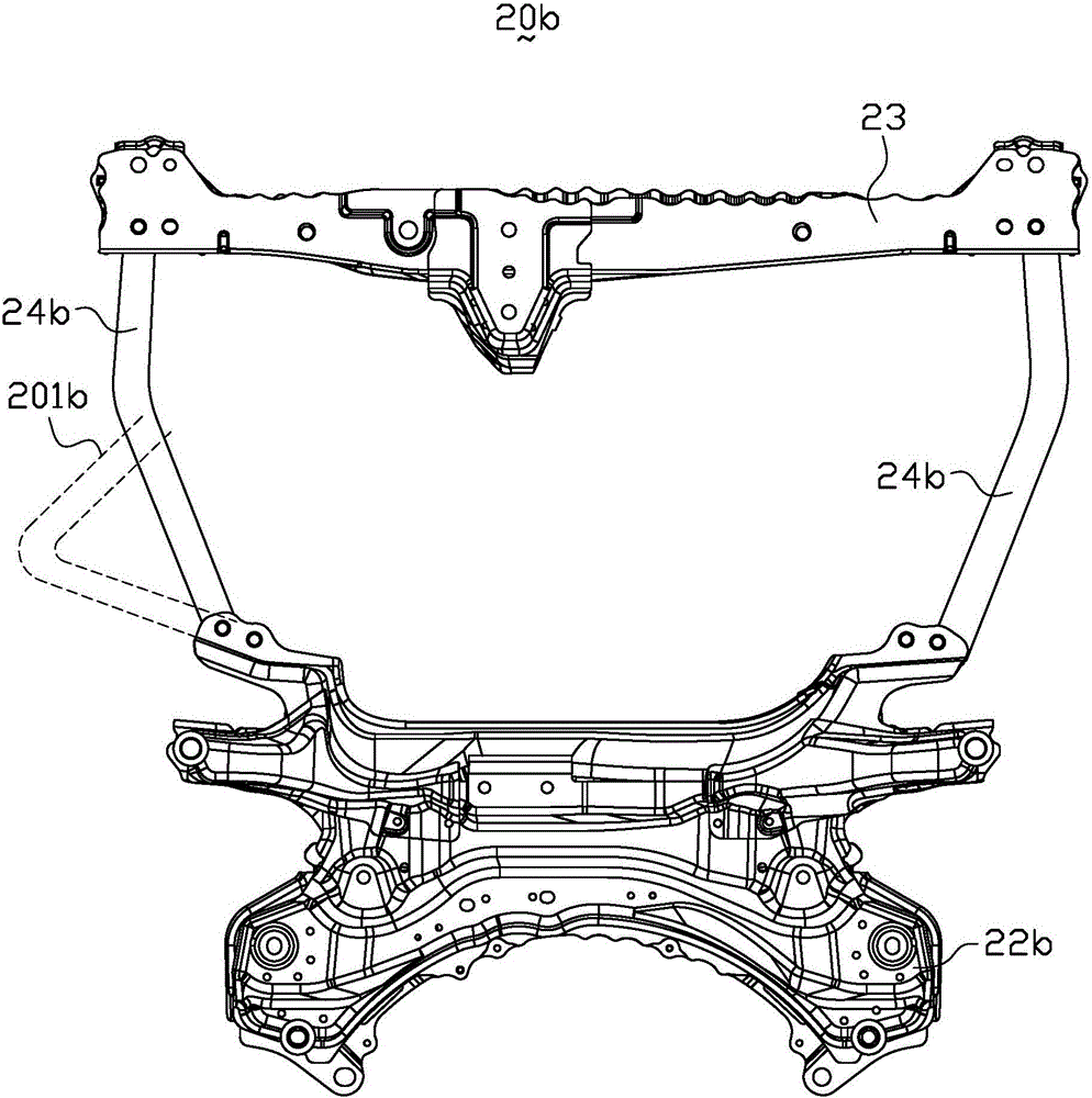
[0005] That is to say, the existing energy-absorbing devices 20a, 20b only bend once during the collision process, and the utilization rate of the energy-absorbing beams 24a, 24b during the collision process is small, that is, the overall bending of the energy-absorbing beams 24a, 24b The number of folds is less, therefore, the energy absorption is less, the vehicle body in the passenger compartment accelerates rapidly during the collision process, and the collision intrusion of the relevant parts of the vehicle body is large
Moreover, when the vehicle body is subjected to a small collision force, the energy-absorbing beams 24a, 24b will deform as a whole, resulting in a serious waste of materials
In addition, if Figure 1a and Figure 1b The collision energy-absorbing device 20a shown, when a collision occurs, the collision energy-absorbing device 20a is deformed in a direction away from the ground as a whole, so that the collision energy-absorbing device 20a is in contact with the powertrain, and the energy of the powertrain is transmitted from the collision energy-absorbing device 20a to The sub-frame, and then transmitted to the body, resulting in increased collision acceleration of the body, and a greater impact on the human body

Method used


Image

  • Collision energy absorption device and automobile
  • Collision energy absorption device and automobile
  • Collision energy absorption device and automobile

Examples


Embodiment Construction

[0032] In order to further explain the technical means and effects that the present invention takes to achieve the intended purpose of the invention, below in conjunction with the accompanying drawings and preferred embodiments, the specific implementation, structure, characteristics and details of the collision energy-absorbing device and the automobile proposed according to the present invention will be described. Its functions are detailed as follows:

[0033] The aforementioned and other technical contents, features and effects of the present invention will be clearly presented in the following detailed description of preferred embodiments with reference to the drawings. Through the description of specific implementation methods, the technical means and effects of the present invention to achieve the intended purpose can be understood more deeply and specifically, but the attached drawings are only for reference and description, and are not used to explain the present inven...


PUM


Abstract

The invention relates to a collision energy absorption device. The collision energy absorption device comprises a front sub-frame, a front cross beam, and two energy absorption beams, wherein the two energy absorption beams are symmetrically arranged, and are connected between the front sub-frame and the front cross beam; the front sub-frame, the front cross beam and the two energy absorption beams are jointly surrounded to form a collision region; each of the energy absorption beams comprises a first side surface next to the collision region and a second side surface opposite to the first side surface; a plurality of bended first induction regions are arranged on the first side surface of each of the energy absorption beams; a plurality of bended second induction regions are arranged on the second side surface of each of the energy absorption surfaces; and the buckling radius of each first induction region of the first side surfaces is less than that of the corresponding second induction region of the corresponding second side surface in the length direction of each energy absorption beam. According to the collision energy absorption device disclosed by the invention, the collision energy absorption efficiency can be improved, the vehicle body collision acceleration is reduced, and impact on a human body is relieved. The invention further relates to an automobile.

Description

technical field [0001] The invention relates to the technical field of automobiles, in particular to a collision energy absorbing device and an automobile. Background technique [0002] Collision safety is an extremely important performance of automobiles, which is directly related to personal safety and also affects the marketing and promotion of vehicles. Usually, when a car is in a frontal collision or an offset collision, it is limited to the space layout and the energy absorption space of the longitudinal beams of the vehicle body is insufficient. It is necessary to add a collision energy absorbing device at the front of the front subframe 22 so that it can absorb energy together with the longitudinal beams of the vehicle body to complete the whole process. Car crash function. [0003] Figure 1a It is a structural schematic diagram of an existing collision energy-absorbing device. Figure 1b It is a side view schematic diagram of the bending structure before and afte...

Claims


Application Information

Patent Timeline
Patent Type & Authority Applications(China)
IPC IPC(8): B62D21/15
CPCB62D21/155B62D21/157
Inventor 宁强富邹新远吴靖刘刚胡思明刘巍
Owner ZHEJIANG GEELY HLDG GRP CO LTD
Why Eureka
Try Eureka