Steering columns for motor vehicles

一种机动车辆、转向柱的技术,应用在转向柱、装在车上的转向控制、车辆部件等方向,能够解决调节行程只能释放、劣化、磨损功能等问题,达到增加操作安全性和功能安全性的效果

Active Publication Date: 2020-10-16
THYSSENKRUPP PRESTA AG +1
View PDF1 Cites 0 Cited by
  • Summary
  • Abstract
  • Description
  • Claims
  • Application Information

AI Technical Summary

Problems solved by technology

However, the coupling of the stop element to the clamping device has the disadvantage that the additional adjustment travel can only be released with certainty if the control lever has actually been pivoted far enough
Moreover, the naturally frequent actuation of the clamping device requires each actuation of the stop device, which may lead to wear and functional degradation

Method used


Image

  • Steering columns for motor vehicles
  • Steering columns for motor vehicles
  • Steering columns for motor vehicles

Examples


Embodiment Construction

[0044] In different figures, identical parts are always provided with the same reference numerals and are therefore usually only described or mentioned once.

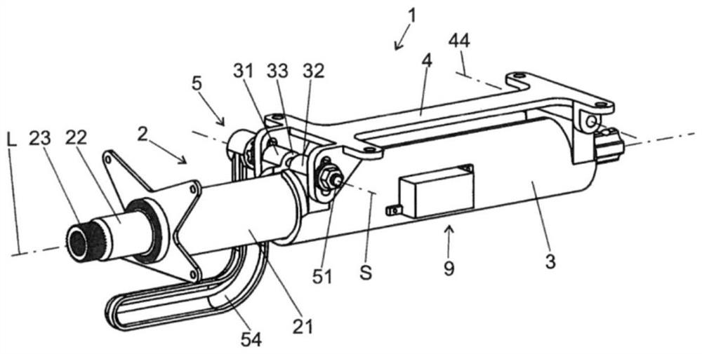
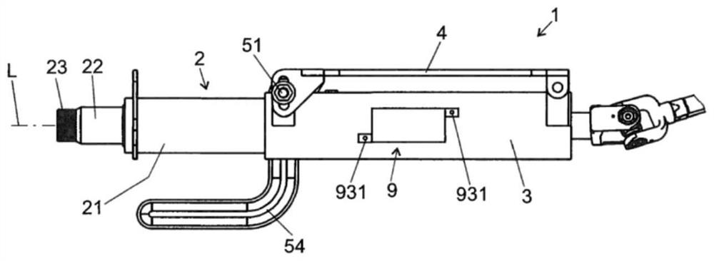
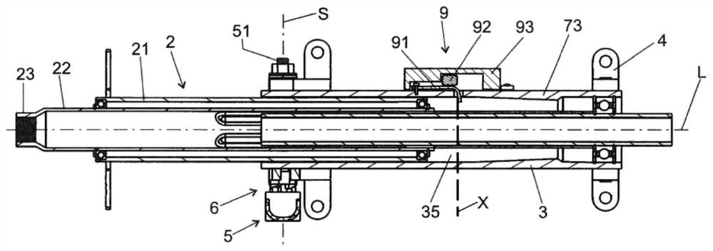
[0045] Figure 1 to Figure 4 A steering column 1 is shown with an adjustment unit 2 with a bushing 21 in which a steering shaft 22 is mounted rotatable about a longitudinal axis L. As shown in FIG. A steering wheel (not shown) may be attached to a portion 23 of the steering shaft 22 at the rear in the direction of travel.

[0046] The adjustment unit 2 is held in a support unit 3 which in turn is attached to a bracket unit 4 which can be attached to the body of a motor vehicle (not shown).

[0047] The support unit 3 comprises a recess with a free movement space 35 in which the adjustment unit 2 is mounted, wherein the support unit 3 comprises sides 31 and 32 between which a slot 33 is located on the longitudinal axis L and a clamping force can be exerted by the clamping device 5 on the sides 31 and 32 transversely to...


PUM


Abstract

A steering column may include an adjustment unit with a steering spindle mounted rotatably about its longitudinal axis in a casing tube, a support unit in which the adjustment unit is mounted so as to be adjustable along the longitudinal axis, and a stop device with a movably mounted stop element positionable in a blocking position and a release position. In the blocking position the stop element limits the adjustment travel of the adjustment unit relative to the support unit. In the release position, the stop element allows adjustability in the direction of the longitudinal axis beyond the adjustment travel limited in the blocking position. The stop device has an actuation body that has an inert mass, is actively connected to the stop element, and is mounted movably relative to the support unit. In a crash event, the mass inertia of the actuation body causes it to interact with the stop element to move the stop element from the blocking position into the release position.

Description

technical field [0001] The invention relates to a steering column for a motor vehicle comprising: [0002] an adjustment unit with a steering shaft mounted rotatably about its longitudinal axis in the sleeve; [0003] a support unit which is connectable to the body of the motor vehicle and wherein the adjustment unit is mounted so as to be adjustable in the direction of the longitudinal axis; and [0004] A stop device with a movably mounted stop element that can be brought into a blocking position or a release position, wherein, in the block position, the stop element limits the adjustment stroke of the adjustment unit relative to the support unit, and in the release position , an adjustability in the direction of the longitudinal axis beyond the limited adjustment travel in the blocking position is permitted. Background technique [0005] In order to adapt the steering wheel position to the seating position of the driver of the motor vehicle, steering columns are known i...

Claims


Application Information

Patent Timeline
Patent Type & Authority Patents(China)
IPC IPC(8): B62D1/19
CPCB62D1/192
Inventor 塞巴斯蒂安·胡贝尔克里斯托夫·蒙丁塞巴斯蒂安·福特
Owner THYSSENKRUPP PRESTA AG
Why Eureka
Try Eureka