
Four-rotation detection platform for automatic optical detection system

A technology of automatic optical inspection and inspection platform, which is applied in optical testing of flaws/defects, material analysis by optical means, measurement devices, etc., can solve the problems of limited imaging angle, high cost, complex structure, etc. Simple structure and convenient installation

Inactive Publication Date: 2016-10-26
CHANGZHOU UNIV +1
View PDF19 Cites 0 Cited by
  • Summary
  • Abstract
  • Description
  • Claims
  • Application Information

AI Technical Summary

Problems solved by technology

In 2015, Shi Yanqiong selected 3 sets of high-resolution cameras arranged at 3 different angles in the design of the optical detection system for surface defects of LCD backlight modules, and the imaging angle was limited and the cost was high; patent 201310071403.0 proposed the use of 3 cameras Arranged at 90°, 60°, and 30° respectively, and two design schemes using one camera and a rotary stage, but no specific structural design scheme for the rotary stage is proposed; patent 201420103362.9 proposes a The single-degree-of-freedom angle-adjustable support plate allows inspectors to observe the backlight module from different angles, and its single-axis adjustment characteristics do not conform to the motion characteristics of visual inspection; patent 201220570304.8 proposes a 4-degree-of-freedom adjustment platform, which can realize The movement of the detected part in two directions and the rotation around two fixed axes are manually controlled; in 2015, Zhang Yudong et al. designed a 5-DOF serial robot to adjust the position and attitude of the camera to obtain a clear image , complex structure and high cost

Method used


Image

  • Four-rotation detection platform for automatic optical detection system

Examples


Embodiment Construction

[0014] The technology of the present invention will be further described below by means of accompanying drawings and examples.

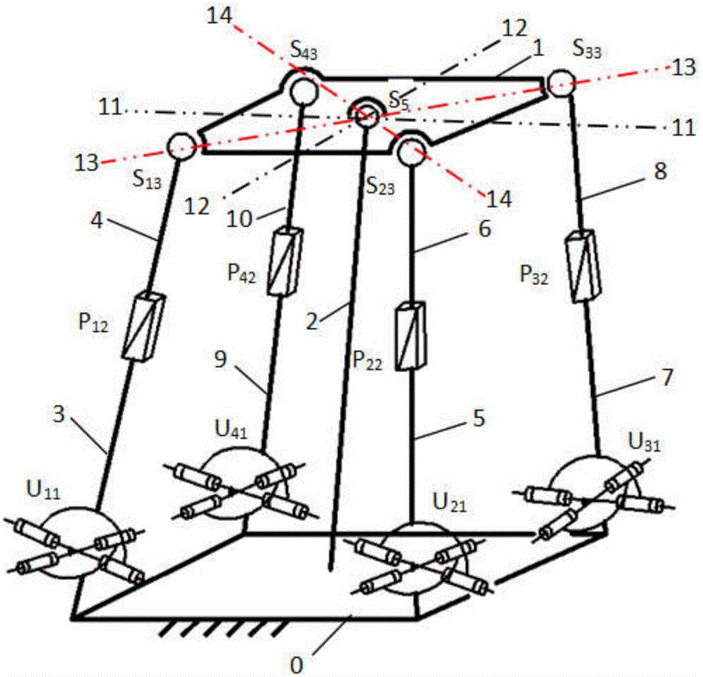
[0015] attached figure 1 The detection platform shown can be one of the embodiments of the present invention, and its technical solution is as follows: a four-rotation detection platform, including a detection platform 1, a static platform 0, and four identical structures connecting these two platforms The UPS branch and an intermediate branch are characterized in that: the intermediate branch is located at the center of the detection platform 1 and the static platform 0, one end of the connecting rod 1 in the intermediate branch is connected with the static platform 0, and the other end is connected with the ball pair a S 5 connection, the ball vice-a S 5 It is connected with the detection platform 1; the four UPS branches are located at the four tops of the static platform 0, and one end of each branch passes through the Hooke hinge U 11 Connect...


PUM


Abstract

The invention relates to a four-rotation detection platform. The four-rotation detection platform comprises a detecting platform (1), a static platform (0), four UPS branches of identical structure and a middle branch, wherein the middle branch is located at the dead center of the detecting platform (1) and the static platform (0), one end of a link I (2) of the middle branch is fixedly connected with the static platform (0), the other end of the link I (2) is connected with a ball pair I (S5), and the ball pair I (S5) is connected with the detecting platform (1); the four UPS branches are all located at four top ends of the static platform (0), one end of each branch is connected with the static platform (0) through a Hooke hinge (U11), each Hooke hinge (U11) is connected with a moving pair I (P12) through a link II (3), each moving pair I (P12) is connected with a ball pair II (S13) through a link III (4), and each ball pair II (S13) is connected with the detecting platform (1); the moving pairs of the four UPS branches are driving pairs. According to the four-rotation detection platform, the rotational degree of freedom for the detecting platform (1) along two central axes of symmetry and two diagonal axes of the detecting platform (1) can be achieved separately, so that the four-rotation detection platform is adaptable to meeting the requirements of an automatic visual detection system on gesture adjustment.

Description

technical field [0001] The invention relates to a four-turn inspection platform for an automatic optical inspection system. Background technique [0002] The surface defect detection method based on automatic optical detection technology is an automatic and high-performance detection method because it does not require or requires less manual intervention. Apply gradually. The quality of the image collected by the image acquisition module in the automatic optical inspection system will not only affect the difficulty of subsequent image processing and analysis, but even determine the success or failure of the entire machine recognition task. [0003] Most of the existing automatic visual inspection systems use unidirectional static imaging, which cannot effectively detect defects under low-resolution conditions due to poor angle projection of the light source or poor placement of the display panel. With the research and development of surface defect detection technology, it ...

Claims


Application Information

Patent Timeline
IPC IPC(8): G01N21/88G01N21/01
CPCG01N21/88G01N21/01
Inventor 朱小蓉邓嘉鸣宋月月许可沈惠平丁少华
Owner CHANGZHOU UNIV
Learn More