A clutch hanger

A clutch and spreader technology, applied in the direction of load hanging components, transportation and packaging, can solve the problems of shaking, easy skew of the clutch, unstable center of gravity, etc.

Active Publication Date: 2017-12-08
山东双林新能源科技有限公司
View PDF3 Cites 1 Cited by
  • Summary
  • Abstract
  • Description
  • Claims
  • Application Information

AI Technical Summary

Problems solved by technology

[0005] In view of the above-mentioned problems existing in the prior art, the object of the present invention is to provide a clutch spreader, which overcomes the problem of easy skewing in the process of hoisting the clutch, avoids shaking and unstable center of gravity during the conveying process, and has high assembly accuracy and is easy to use. Convenience, simple operation, safe and reliable, realize efficient pressing operation

Method used


Image

  • A clutch hanger
  • A clutch hanger
  • A clutch hanger

Examples


Embodiment Construction

[0036] Specific embodiments of the present invention will be described in detail below in conjunction with the accompanying drawings. It should be understood that the specific embodiments described here are only used to illustrate and explain the present invention, and are not intended to limit the present invention.

[0037]For the convenience of description, spatially relative terms may be used here, such as "on ...", "over ...", "on the surface of ...", "above", etc., to describe the The spatial positional relationship between one device or feature shown and other devices or features. It will be understood that the spatially relative terms are intended to encompass different orientations of the device in use or operation in addition to the orientation depicted in the figures. For example, if the device in the figures is turned over, devices described as "above" or "above" other devices or configurations would then be oriented "beneath" or "above" the other devices or confi...


PUM


Abstract

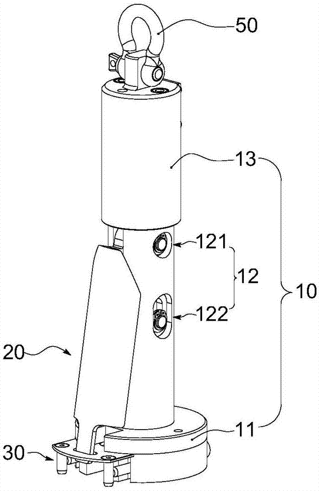
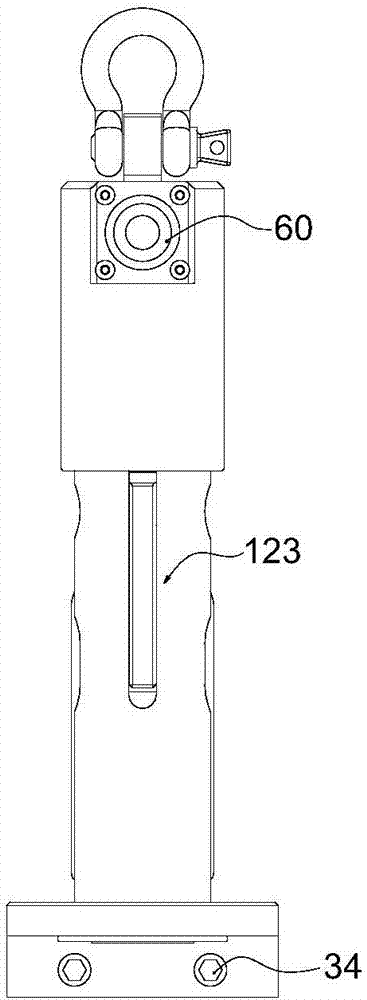
The invention relates to a clutch lifting sling and belongs to the field of transport equipment of automobile assembly lines. The clutch lifting sling comprises a lifting sling body, a driving part fixed to the lifting sling body, a locking part which is fixed to the lifting sling body and used for locking or releasing the driving part and a sliding part which can be fixed to the lifting sling body in a telescopic mode and provide releasing driving force. The locking part is fixed to one end of the lifting sling body and extends in the radial direction of the lifting sling body. One end of the driving part is connected with the lifting sling body, and the other opposite end of the driving part extends outwards and is intersected with the extending end of the locking part, and the other opposite end of the driving part and the extending end of the locking part can be connected movably. The sliding part is fixed into the lifting sling body, arranged at the top of the driving part and capable of being arranged in a telescopic mode relative to the driving part. The driving force for unlocking the locking state of the locking part is provided through stretching out and drawing back of the sliding part, accordingly, the locking part is unlocked from the locking state, and a clutch is disengaged from the lifting sling body. The assembly precision in the whole lifting process is high, using is convenient, operation is simple, and safety and reliability are achieved.

Description

technical field [0001] The invention belongs to the transportation equipment of the automobile assembly line, and more specifically relates to a sling suitable for a clutch and capable of automatic clamping. Background technique [0002] At present, conveying fixtures are often used in automobile assembly production lines. On the clutch delivery line, it is generally necessary to lift the clutch and then go to the production line for assembly. The hangers in the prior art basically use claws to hook the edge of the clutch or Insert it into the hole on the clutch for lifting. [0003] The disadvantage of the prior art is that, first of all, no matter whether the claw hooks the edge of the clutch or is inserted into the hole on the clutch, after the lifting is completed, when the clutch is assembled with other parts of the gearbox, the claws are likely to interfere with other parts of the gearbox , therefore, when the claw is disengaged from the clutch, it will inevitably cau...

Claims


Application Information

Patent Timeline
Patent Type & Authority Patents(China)
IPC IPC(8): B66C1/62B66C1/66
CPCB66C1/62B66C1/66
Inventor 邬建斌王鹏林慧明
Owner 山东双林新能源科技有限公司
Why Eureka
Try Eureka