Workbench bolt lock structure for machining equipment

A processing equipment and workbench technology, applied in metal processing equipment, metal processing machinery parts, manufacturing tools, etc., can solve the problems of difficulty in reducing the size of drive transmission, excessive overall size of equipment, and easy interference in processing, etc.

Inactive Publication Date: 2016-11-09
陈广生
View PDF6 Cites 1 Cited by
  • Summary
  • Abstract
  • Description
  • Claims
  • Application Information

AI Technical Summary

Problems solved by technology

However, in the case of a larger table size, the drive of the latch requires a larger feed distance, which makes it difficult to downsize the drive transmission
Larger size will cause the overall size of the equipment to be too large and easily interfere with processing operations

Method used


Image

  • Workbench bolt lock structure for machining equipment
  • Workbench bolt lock structure for machining equipment
  • Workbench bolt lock structure for machining equipment

Examples


Embodiment Construction

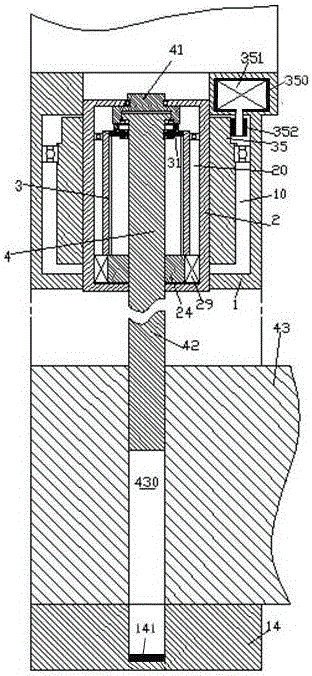
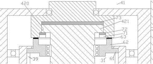
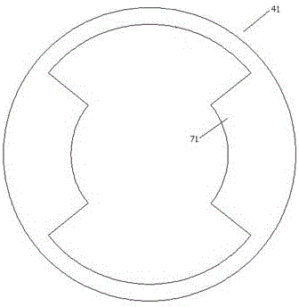
[0009] Combine below Figure 1-3 The present invention will be described in detail.

[0010] The workbench latch structure for processing equipment according to the embodiment of the present invention includes a housing 1 fixedly connected with the frame, a threaded sleeve drive motor 351 mounted on the housing 1, and an axial direction through a bearing. The threaded ring gear sleeve 35 fixedly installed in the chamber 10 of the housing 1, the threaded sleeve 2 matched by the internal thread of the threaded ring gear sleeve 35, the threaded sleeve 2 axially fixedly installed on the threaded sleeve 2 The internal screw drive motor 29 in the inner cavity 20, the internal screw block 24 that is driven rotatably and axially fixed by the internal screw drive motor 29 in the circumferential direction, and the internal screw component threaded by the internal thread block 24 4. Wherein, the threaded sleeve drive motor 351 engages with the threaded gear ring sleeve 35 through a powe...


PUM


Abstract

A workbench bolt lock structure for machining equipment comprises a shell (1) fixedly connected with a rack, a threaded sleeve driving motor (351) mounted on the shell (1), a threaded gear ring sleeve (35), a threaded sleeve (2), an internal screw part driving motor (29), an internal threaded block (24) and an internal screw part (4). The threaded gear ring sleeve (35) is axially and fixedly mounted in a chamber (10) of the shell (1) through a bearing. The threaded sleeve (2) is matched with an internal thread of the threaded gear ring sleeve (35). The internal screw part driving motor (29) is axially and fixedly mounted in an inner cavity (20) of the threaded sleeve (2). The internal threaded block (24) can be circumferentially driven by the internal screw part driving motor (29) to rotate and is axially fixed. The internal screw part (4) is in threaded fit with the internal threaded block (24).

Description

technical field [0001] The invention relates to the field of locking devices, in particular to a workbench latch structure for processing equipment. Background technique [0002] In the field of machining, the table can be disassembled to facilitate the clamping and installation of workpieces. However, the fixing of the disassembled workbench needs additional operations to complete. This causes inconvenience to the production operation and easily causes a decrease in production efficiency. The material power operated latch provides secure and quick fixation of the workbench. However, in the case of a larger table size, the drive of the latch requires a larger feed distance, which makes it difficult to downsize the drive transmission. A larger size would result in an overall oversized device and would easily interfere with machining operations. Contents of the invention [0003] The object of the present invention is to provide a worktable latch structure for processing...

Claims


Application Information

Patent Timeline
Patent Type & Authority Applications(China)
IPC IPC(8): B23Q1/28B23Q1/30
CPCB23Q1/28B23Q1/30
Inventor 陈广生
Owner 陈广生
Why Eureka
Try Eureka