Device for reducing locking resistance of door leaf of civil defense door

A technology for civil air defense doors and door leaves, which is applied in sealing devices, building locks, buildings, etc. It can solve the problems of increased operating resistance of the locking mechanism, which is not conducive to the locking and sealing of the door leaf and the door frame, so as to reduce the operating force and labor intensity Effect

Inactive Publication Date: 2016-11-09
贵州瑞安达人防设备有限公司
View PDF4 Cites 2 Cited by
  • Summary
  • Abstract
  • Description
  • Claims
  • Application Information

AI Technical Summary

Problems solved by technology

Due to the sliding friction between the slope of the lock head and one side of the lock groove of the door frame, a large resistance is produced, which increases the operating resistance of the locking mechanism, which is not conducive to the locking and sealing of the door leaf and the door frame

Method used


Image

  • Device for reducing locking resistance of door leaf of civil defense door
  • Device for reducing locking resistance of door leaf of civil defense door
  • Device for reducing locking resistance of door leaf of civil defense door

Examples


Embodiment 1

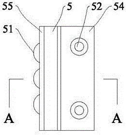
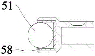
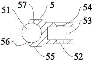
[0029] See attached figure 1 And attached figure 2 , the first card holder 5 is a rectangular support, with a strip-shaped head 55 and a strip-shaped tail 54, the end surface of the strip-shaped head 55 is provided with a spherical groove 57, the spherical groove The steel ball 51 is movably embedded in the 57, and the end surface of the elongated tail 54 is provided with a slot 53 along the length direction, and the slot 53 is provided with two sets of screw holes 52 that pass through. The locking slot 53 is inserted into a part of the locking side of the locking slot 41 by a sleeve. Three steel balls 51 of the same specification are arranged on the end face of the elongated head 55 along the length direction. The opening of the spherical groove 57 is provided with a card edge 56 to prevent the steel ball 51 from slipping off. The card edge 56 can be formed by tapping the opening edge of the groove 57 after the steel ball 51 is loaded to make the opening deform and shrink....

Embodiment 2

[0035] See attached Image 6 And attached Figure 7 , the second deck 7 is basically the same as the first deck 5, and is also a rectangular support with a strip-shaped head 73 and a strip-shaped tail 74, and the middle of the strip-shaped head 73 Roller grooves 75 are provided in the transverse direction, and lugs 76 are formed at both ends. The lugs 76 are provided with pin holes penetrating through them. Also, a slot 53 is provided on the end face of the elongated tail 74 along the length direction. The slot 53 is provided with Two sets of screw holes 52 pass through oppositely, and the locking groove 53 is sleeved on a part of the locking edge of the locking groove 41 .

[0036] The roller 71 is placed in the roller groove 75 and connected with the ear plate 76 with holes through the pin shaft 72, wherein the roller 71 rotates on the pin shaft 72, and the pin shaft holes of the pin shaft 72 and the ear plate 76 do not rotate mutually.


PUM


Abstract

The invention discloses a device for reducing the locking resistance of a door leaf of a civil defense door. The device comprises the door leaf (1), a lock seat (2) connected to the door leaf (1), a lock head (3) connected with a locking connecting rod mechanism and conducting the stretching and contacting movement in a hole of the lock seat (2), and a door frame (4). A lock groove (41) is formed in the door frame (4), a slope (31) is arranged on the stretching-out part of the lock head (3), and the slope (31) and the locking edge of the lock groove (41) generate the sliding friction movement. The device is characterized in that the locking edge of the lock groove (41) is fixedly connected with a first clamping seat (5) or a second clamping seat (7), a steel ball (51) is arranged on the first clamping seat (5) or a roller (71) is arranged on the second clamping seat (7), and the slope (31) stretches out to generate the rolling friction movement with the steel ball (51) or the roller (71). According to the device, the locking force of the door leaf is improved under the same operation force condition or the operation force is reduced under the same locking force condition, and the device is used for greatly lowering the labor intensity of manual locking operation especially for locking of large heavy-load civil defense doors.

Description

technical field [0001] The invention relates to air defense door equipment, in particular to a device for reducing the locking resistance of a door leaf of an air defense door. Background technique [0002] Civil defense doors are widely used in civil buildings and public places to provide shelters in wartime and prevent damage caused by shock waves and poisonous gases. [0003] The air defense door includes a pre-buried door frame, a door leaf installed on the door frame, a locking mechanism on the door leaf, and a sealing structure on the door frame and the door leaf. The locking force of the civil air defense door is an important indicator to ensure the airtightness of the civil air defense door. The method widely used in the existing civil air defense door locking is to make the lock head with an inclined surface protrude through the locking mechanism, and the lock head located on the lock head The inclined surface is in contact with one side of the lock groove located ...

Claims


Application Information

Patent Timeline
Patent Type & Authority Applications(China)
IPC IPC(8): E05B15/02E05B15/10E05B17/00E06B7/22
CPCE05B15/022E05B15/10E05B17/007E06B7/22
Inventor 刘胜马龙刘康辉
Owner 贵州瑞安达人防设备有限公司
Why Eureka
Try Eureka