
Slotted point-tail screws

A technology for cutting grooves and screws, which is applied in the direction of screws, threaded fasteners, connecting components, etc., and can solve problems such as chip extrusion, deflection, and large locking resistance

Active Publication Date: 2022-08-02
ESSENCE METHOD REFINE
View PDF8 Cites 0 Cited by
  • Summary
  • Abstract
  • Description
  • Claims
  • Application Information

AI Technical Summary

Problems solved by technology

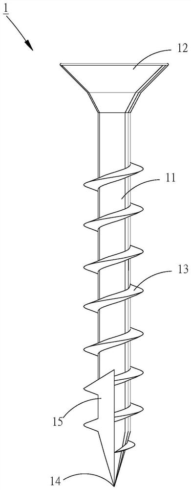
[0002] refer to figure 1 , the existing screw 1 includes a rod body 11, a screw head 12 located at one end of the rod body 11, and a right-handed thread 13 on the rod body 11 with a helical ring, wherein the other end of the rod body 11 tapers to form a The tip 14, and the rod body 11 is provided with a cutting groove 15; when in use, use a tool (not shown) to rotate the screw head 12 to lock the screw teeth 13 into an object (not shown) Inside, the cutting groove 15 cuts the object, and the chips produced by cutting are accommodated in the cutting groove 15 to complete the locking; however, the opening of a single cutting groove 15 generally extends in a clockwise direction, which is similar to that of a right-handed screw thread. 13 have the same direction of rotation, but the cutting effect is limited and wood fibers cannot be effectively cut off. In addition, the chip removal effect and the chip space are limited. The process has a large locking resistance, and even the chips are easy to be extruded due to excessive accumulation, so that the cracking of the material and the slowing down of the locking speed occur; even if the screw 1 can be screwed into the object, the cutting The groove 15 cannot press the remaining chips downwardly, so the locking effect can not be improved relatively; moreover, because only the tip 14 abuts against the object, the force-bearing area is small, so it is easy to apply force improperly when drilling the lock. The deflection occurs, causing the tip 14 to deviate from the original abutting position, so the user needs to re-align the screw 1 to perform locking, which is not only time-consuming and laborious, so there is still room for improvement

Method used


Image

  • Slotted point-tail screws
  • Slotted point-tail screws
  • Slotted point-tail screws

Examples


Embodiment Construction

[0086] The above and other technical contents, features and effects of the present invention will be clearly and clearly shown in the following detailed description of the preferred embodiments with reference to the drawings.

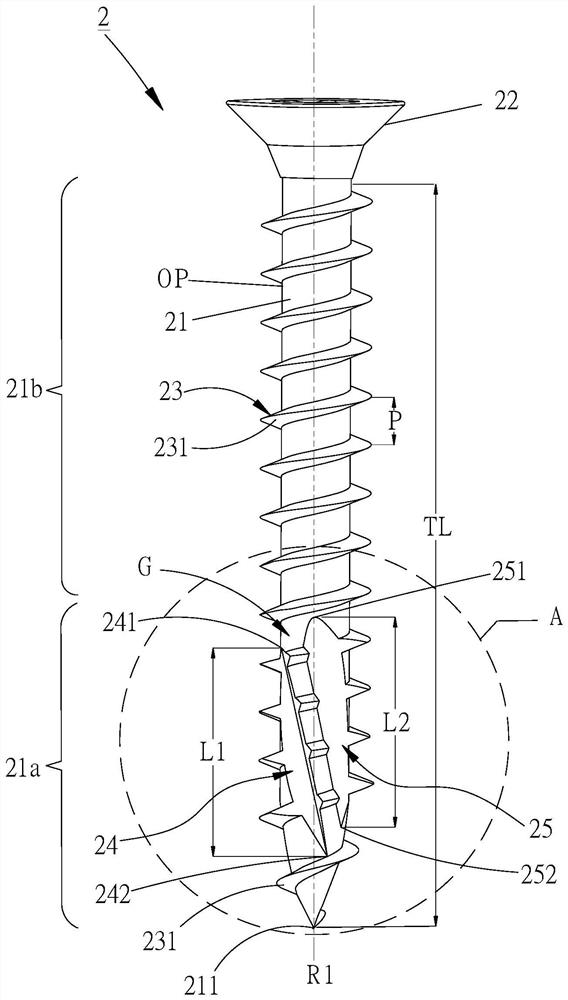
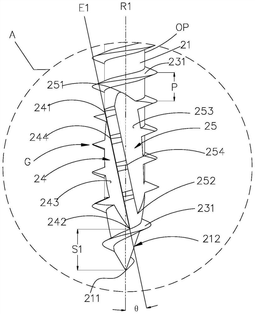
[0087] see figure 2 , the first preferred embodiment of the present invention, the pointed end screw 2 with the slot includes a rod body 21, a screw head 22 provided at one end of the rod body 21, and a screw thread portion provided on the rod body 21 by a helical ring 23; wherein, the screw portion 23 has a plurality of screw teeth 231 (as shown in the figure, right-handed screw teeth 231), any two adjacent screw teeth 231 are spaced apart to form a pitch P, and the rod body 21 can be The rod body 21 is round rod-shaped and has an outer peripheral surface OP. The other end of the rod body 21 is tapered to form a tip 211 opposite to the screw head 22. The rod body 21 defines a longitudinal axis R1 passing through the tip 211 and also defines a A lengt...


PUM


Abstract

The invention discloses a pointed-tail screw with a notch, which mainly has a tip on a rod body and defines a longitudinal axis passing through the tip. The rod body is screwed with a plurality of rightward helical threads and is provided with a first spaced apart first screw. A slot and a second slot, a first edge of the first slot is parallel to a second edge of the second slot, while the first edge extends toward the head of the screw , and its extension direction is opposite to the right-handed direction of the threads; the reverse extension of the above-mentioned grooves is beneficial to the initial cutting of the drill and lock, so as to achieve rapid chip removal, avoid cracked materials and press the chips to improve the locking force. .

Description

technical field [0001] The invention relates to a screw, in particular to a pointed tail screw with a slot. Background technique [0002] see figure 1 , the existing screw 1 comprises a rod body 11, a screw head 12 provided at one end of the rod body 11, and a right-handed screw thread 13 spirally arranged on the rod body 11, wherein the other end of the rod body 11 is tapered to form a The tip 14, and the rod body 11 is provided with a groove 15; when in use, use a tool (not shown in the figure) to rotate the screw head 12 to interlock the screw teeth 13 to lock into an object (not shown in the figure) Inside, the cutting groove 15 cuts the object, and the chips generated by the cutting are accommodated in the cutting groove 15 to complete the locking; however, the opening of the single cutting groove 15 generally extends clockwise, which is consistent with the right-hand thread. The rotation direction of 13 is the same, but its cutting effect is limited and cannot effect...

Claims


Application Information

Patent Timeline
IPC IPC(8): F16B25/04F16B25/10
CPCF16B25/103F16B25/0084
Inventor 陈翎芳
Owner ESSENCE METHOD REFINE
Learn More