AI technical title is built by Patsnap AI team. It summarizes the technical point description of the patent document.
An experimental device and micro-flow technology, which can be used in surveying, wellbore/well components, earth-moving drilling, etc., and can solve the problem of difficulty in obtaining micro-flow detection data.
Active Publication Date: 2019-05-03
CHONGQING UNIVERSITY OF SCIENCE AND TECHNOLOGY
View PDF5 Cites 0 Cited by
Summary
Abstract
Description
Claims
Application Information
AI Technical Summary
This helps you quickly interpret patents by identifying the three key elements:
Problems solved by technology
Method used
Benefits of technology
Problems solved by technology
[0003] In view of the above problems, the purpose of the present invention is to provide a micro-flow detection experimental device to solve the problem that the on-site micro-flow detection data is difficult to obtain
Method used
Image
Click on the blue label to locate the original text in one second.
Reading with bidirectional positioning of images and text.
Examples
Embodiment Construction
[0017] In the following description, for purposes of explanation, numerous specific details are set forth in order to provide a thorough understanding of one or more embodiments. It may be evident, however, that these embodiments may be practiced without these specific details.
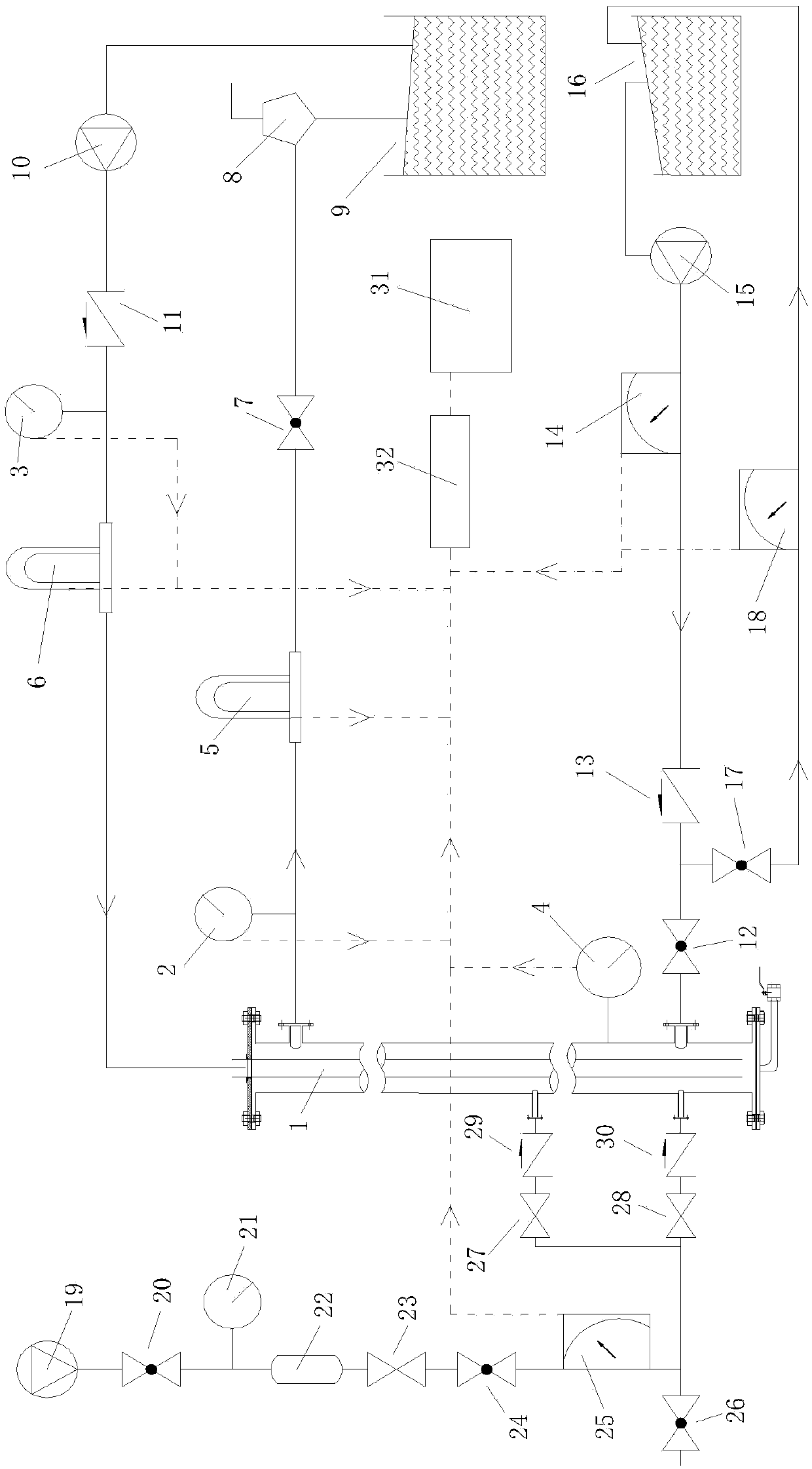
[0018] figure 1 The piping of the micro-flow detection experimental device according to the embodiment of the present invention is shown.
[0019] Such as figure 1 As shown, the micro-flow detection experimental device of the present invention includes: a wellbore 1, a drilling fluid circulation pipeline, a water overflow pipeline, a leakage pipeline, a gas overflow pipeline and a data acquisition system. The wellbore, the four types of pipelines and the data acquisition system will be described respectively below.
[0020] 1. Shaft
[0021] The wellbore 1 includes the inlet and outlet of the top section, the liquid overflow port and the leakage port of the bottom section, and two gas overflow por...
PUM
Abstract
The invention provides a micro flow detection experiment device. The micro flow detection experiment device comprises a shaft, a drilling fluid circulating pipeline, a water overflow pipeline, a leakage loss pipeline, a gas overflow pipeline and a data acquisition system. The drilling fluid circulating pipeline comprises a first pressure transmitter, a second pressure transmitter, a third pressure transmitter, a first mass flow meter, a second mass flow meter, a first ball valve, a gas-liquid separator, a first water storage tank, a first screw pump and a first non-return valve. The water overflow pipeline comprises a second ball valve, a second non-return valve, a first rotor flow meter, a second screw pump and a second water storage tank. The leakage loss pipeline comprises a third ball valve and a second rotor flow meter. The gas overflow pipeline comprises an air compressor, a fourth ball valve, a pressure gauge, a volume tank, a needle valve, a fifth ball valve, a third rotor flow meter, a sixth ball valve, a first stop valve, a second stop valve, a third non-return valve and a fourth non-return valve. The data acquisition system comprises a computer and an A / D converter. By means of the micro flow detection experiment device, overflow or leakage loss can be accurately and timely judged.
Description
technical field [0001] The invention relates to the technical field of drilling equipment, and more specifically, to an experimental device for micro-flow detection. Background technique [0002] With the development of oil exploration and development towards more complex deep formations, the problem of narrow density safety window encountered in the drilling process is becoming more and more prominent, which seriously restricts the development of oil exploration. Micro-flow controlled pressure drilling technology is an improved managed pressure drilling technology, which combines the advantages of underbalanced drilling and conventional drilling technology. Accurate formation pressure value, timely feedback control to keep the bottom hole pressure within the safety window, effectively ensuring drilling safety. Contents of the invention [0003] In view of the above problems, the purpose of the present invention is to provide an experimental device for micro-flow detectio...
Claims
Application Information
Patent Timeline
Application Date:The date an application was filed.
Publication Date:The date a patent or application was officially published.
First Publication Date:The earliest publication date of a patent with the same application number.
Issue Date:Publication date of the patent grant document.
PCT Entry Date:The Entry date of PCT National Phase.
Estimated Expiry Date:The statutory expiry date of a patent right according to the Patent Law, and it is the longest term of protection that the patent right can achieve without the termination of the patent right due to other reasons(Term extension factor has been taken into account ).
Invalid Date:Actual expiry date is based on effective date or publication date of legal transaction data of invalid patent.
Patent Type & AuthorityPatents(China)
IPC IPC(8): E21B47/00E21B47/06E21B47/10
CPCE21B47/00E21B47/06E21B47/10
Inventor雷宗明王冬平赵士林黄靖富蔡文涛王伟何彦希
OwnerCHONGQING UNIVERSITY OF SCIENCE AND TECHNOLOGY

