
A static load test loading device for a steel structure frame

A loading device and static load test technology, which is applied in the testing of machines/structural components, measuring devices, testing of mechanical components, etc., can solve the problems of long loading accumulation time, instability of steel structure frame, high risk factor, etc., to achieve Strong economy, low input cost, convenient processing and production, installation and disassembly

Active Publication Date: 2019-07-02
JIANGSU TESTING CENT FOR QUALITY OF CONSTR ENG +1
View PDF7 Cites 0 Cited by
  • Summary
  • Abstract
  • Description
  • Claims
  • Application Information

AI Technical Summary

Problems solved by technology

[0002] At present, in the experimental research in the field of civil engineering, many static loading tests are required. For vertical loading of the steel structure frame, the common loading method is to use hanging heavy objects or stacking heavy objects to realize the steel structure frame. However, when the load is large, it is easy to cause the steel structure frame to be unstable, prone to danger, the risk factor is high, the loading accumulation time is long and the workload is large

Method used


Image

  • A static load test loading device for a steel structure frame
  • A static load test loading device for a steel structure frame

Examples


Embodiment Construction

[0014] The preferred embodiments of the present invention will be described below in conjunction with the accompanying drawings. It should be understood that the preferred embodiments described here are only used to illustrate and explain the present invention, and are not intended to limit the present invention.

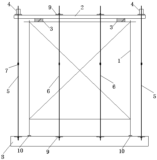
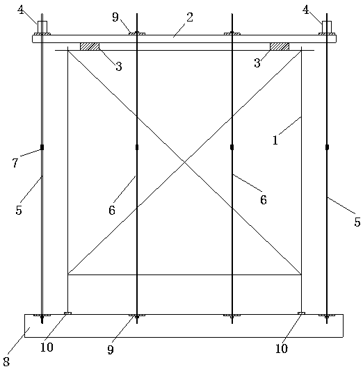
[0015] like figure 1 As shown, a static load test loading device for a steel structure frame includes a load cell 10 located directly below the test steel structure frame and a loading mechanism installed on the test steel structure frame. The loading mechanism includes a loading beam 2, a distribution Beam 3, synchronous hydraulic jack 4, active steel tie rod 5, limit steel tie rod 6, reaction force base 8, steel backing plate 9, loading beam 2 and distribution beam 3 are fastened by bolts at the cross node positions, so that the loading mechanism The upper part is formed as a whole to ensure the safety of loading and to facilitate the movement of the distribution ...


PUM


Abstract

The invention discloses a loading device for a static load test of a steel structure frame body, and the device comprises force sensors located exactly under the steel structure frame body, and a loading mechanism installed on the steel structure frame body. The device is characterized in that the loading mechanism comprises a loading beam, a distribution beam, hydraulic jacks, active steel pull rods, limiting steel pull rods, a counter-force pedestal, a steel base plate, and a steel sleeve; the loading beam and the distribution beam are connected and fastened at an intersection node through a bolt, thereby enabling the upper part of the loading mechanism to form an integrated body; the loading beam is connected with the counter-force pedestal located at the lower part through four active steel pull rods located at four corners of the loading beam and four limiting steel pull rods located at the central part of the loading beam; a part, at which the loading beam is located, of each active steel pull rod is provided with one hydraulic jack; and the force sensors are respectively disposed under vertical columns at four corners of the steel structure frame body. The device can achieve the loading of a load, can accurately measure the actual loading force of each vertical column, is reliable in force bearing, is simple, is convenient to operate, and is safety in loading.

Description

technical field [0001] The invention belongs to the technical field of load test loading, and in particular relates to a loading device for a static load test of a steel structure frame. Background technique [0002] At present, in the experimental research in the field of civil engineering, many static loading tests are required. For vertical loading of the steel structure frame, the common loading method is to use hanging heavy objects or stacking heavy objects to realize the steel structure frame. However, when the added load is large, it is easy to cause the steel structure frame to become unstable, prone to danger, the risk factor is high, the loading accumulation time is long and the workload is heavy. Contents of the invention [0003] The present invention aims to overcome the defects of the prior art. The present invention provides a static load test loading device for a steel structure frame. The loading device composed of force bearings is used for loading vert...

Claims


Application Information

Patent Timeline
Patent Type & Authority Patents(China)
IPC IPC(8): G01M13/00
CPCG01M13/00
Inventor 孙正华张彪崇金玲魏晓斌蔡志军
Owner JIANGSU TESTING CENT FOR QUALITY OF CONSTR ENG
Learn More