
Slot Antenna and Smart Terminal

A technology for slot antennas and smart terminals, which is applied to slot antennas, antennas, and devices that enable antennas to work in different bands at the same time, and can solve the problems of larger antennas and different carrier aggregation requirements

Active Publication Date: 2018-09-11
GUANGDONG OPPO MOBILE TELECOMM CORP LTD
View PDF8 Cites 0 Cited by
  • Summary
  • Abstract
  • Description
  • Claims
  • Application Information

AI Technical Summary

Problems solved by technology

[0003] The purpose of the present invention is to provide a slot antenna and an intelligent terminal to solve the problems in the prior art that setting switches in the slot makes the overall size of the antenna larger and does not meet the technical requirements of carrier aggregation

Method used


Image

  • Slot Antenna and Smart Terminal
  • Slot Antenna and Smart Terminal
  • Slot Antenna and Smart Terminal

Examples


Embodiment Construction

[0031] In order to make the object, technical solution and advantages of the present invention more clear, the present invention will be further described in detail below in conjunction with the accompanying drawings and embodiments. It should be understood that the specific embodiments described here are only used to explain the present invention, not to limit the present invention.

[0032] In order to illustrate the technical solutions of the present invention, specific examples are used below to illustrate.

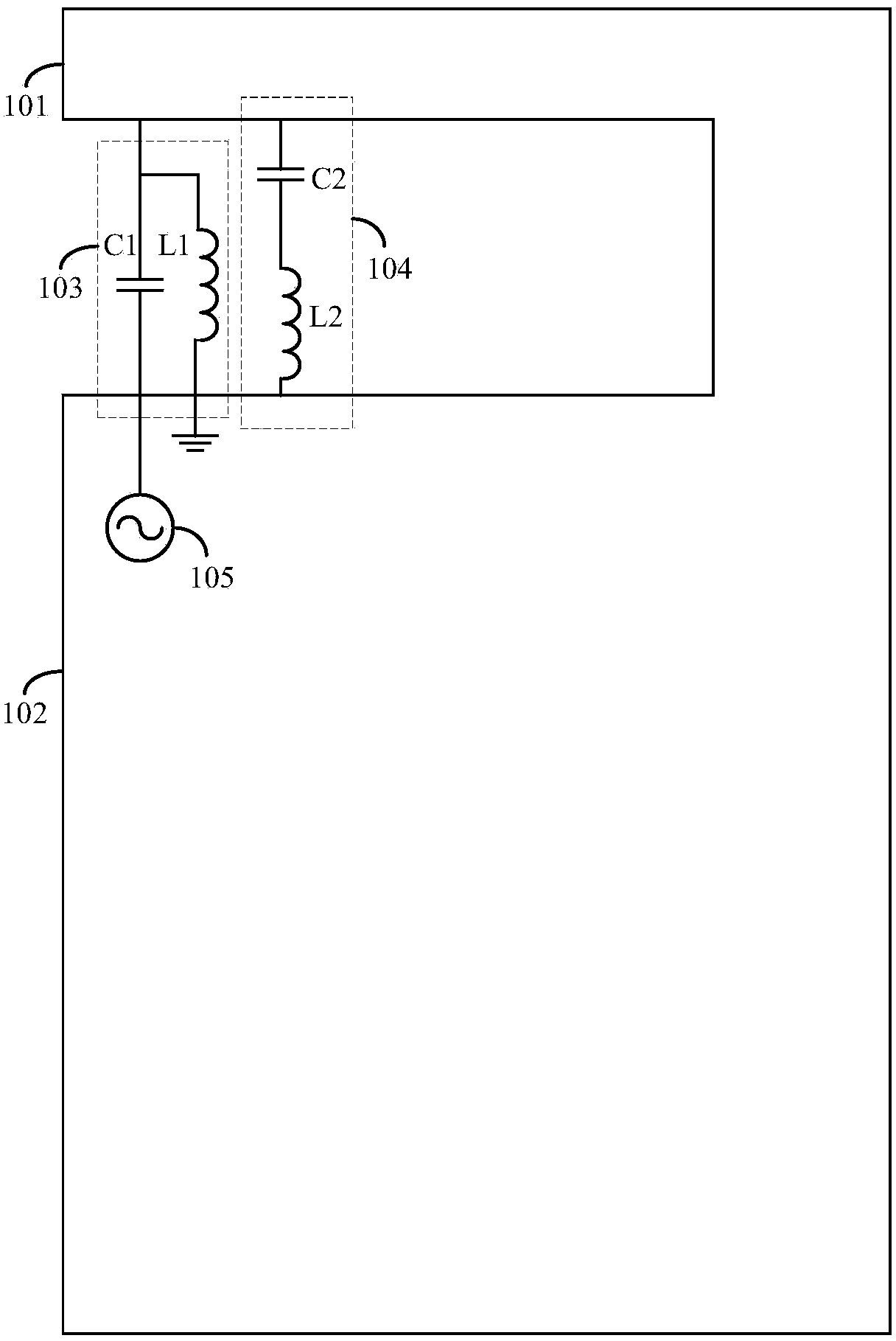
[0033] An embodiment of the present invention provides a slot antenna, such as image 3 As shown, the slot antenna includes a metal plate, a low frequency resonant circuit 103 and a high frequency resonant circuit 104;

[0034] The metal plate includes a ground terminal 101 and an antenna terminal 102. A gap is formed between the ground terminal 101 and the antenna terminal 102. The low-frequency resonant circuit 103 and the high-frequency resonant circuit 104 are re...


PUM


Abstract

The invention is applicable to the technical field of antennas, and provides a slot antenna and an intelligent terminal. The slot antenna comprises a metal board, a low-frequency resonant circuit and a high-frequency resonant circuit, wherein the metal board comprises a ground end and an antenna end, a slot is formed between the ground end and the antenna end, and the low-frequency resonant circuit and the high-frequency resonant circuit are respectively connected onto two sides of the slot for realizing carrier aggregation between the low frequency band and the high frequency band. Through arranging the high-frequency resonant circuit and the low-frequency resonant circuit in the middle of the slot and working in a time-sharing or simultaneous mode via an independent feeder, an impedance matching network and a feed point, the high and low-frequency radiation performance of the slot antenna is improved, and the work requirements of the carrier aggregation technology and the size requirements of the intelligent terminal are met at the same time.

Description

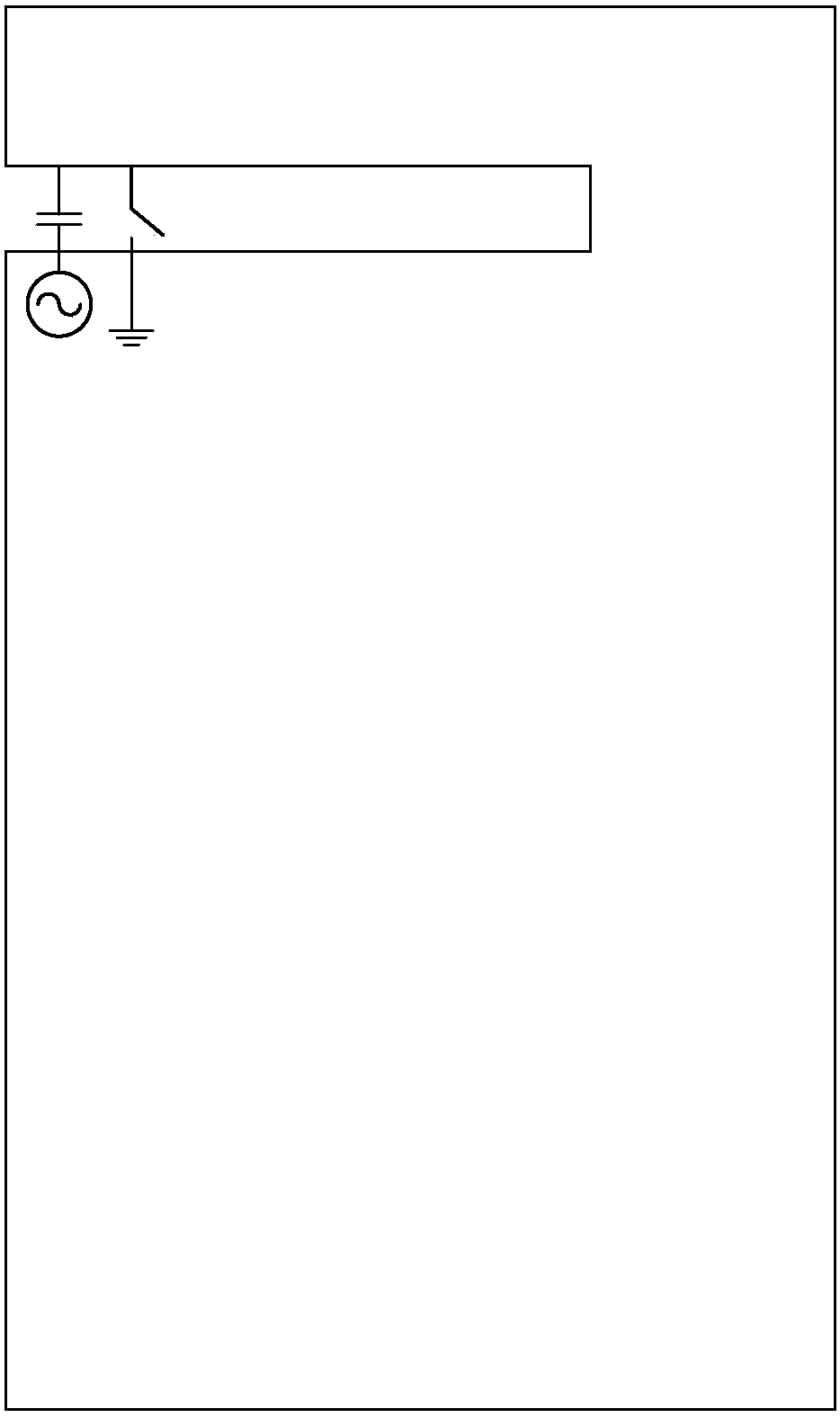
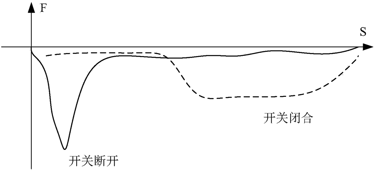
technical field [0001] The invention relates to the technical field of antennas, in particular to a slot antenna and an intelligent terminal. Background technique [0002] Conventional slot antenna design methods, such as figure 1 As shown, capacitors and switches are respectively set in the gap, and high frequency or low frequency can be realized through switch switching, such as figure 2 As shown, the high frequency is realized when the switch is turned off, and the low frequency is realized when the switch is closed. However, setting the switch will increase the overall size of the antenna and cannot meet the technical requirements of carrier aggregation. In summary, the existing technology Setting the switch in the slot increases the volume of the antenna as a whole and does not meet the technical requirements of carrier aggregation. Contents of the invention [0003] The object of the present invention is to provide a slot antenna and an intelligent terminal, so as...

Claims


Application Information

Patent Timeline
Patent Type & Authority Patents(China)
IPC IPC(8): H01Q13/10H01Q5/10H01Q5/328H01Q1/36
CPCH01Q1/36H01Q5/10H01Q5/328H01Q13/10
Inventor 王新宝顾亮
Owner GUANGDONG OPPO MOBILE TELECOMM CORP LTD
Learn More