

Slot antenna and intelligent terminal
A technology for slot antennas and smart terminals, which is applied to slot antennas, antennas, and devices that enable antennas to work in different bands at the same time, and can solve problems such as carrier aggregation with different requirements and antenna volume becoming larger
- Summary
- Abstract
- Description
- Claims
- Application Information
AI Technical Summary
Problems solved by technology
Method used
Image

Examples
Embodiment Construction
[0031] In order to make the object, technical solution and advantages of the present invention more clear, the present invention will be further described in detail below in conjunction with the accompanying drawings and embodiments. It should be understood that the specific embodiments described here are only used to explain the present invention, not to limit the present invention.
[0032] In order to illustrate the technical solutions of the present invention, specific examples are used below to illustrate.
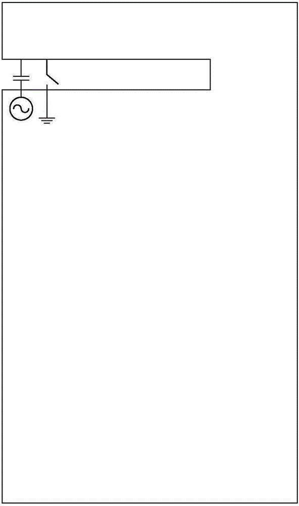
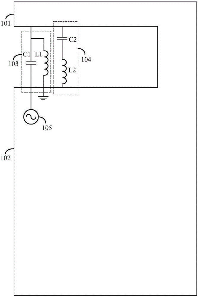
[0033] An embodiment of the present invention provides a slot antenna, such as image 3 As shown, the slot antenna includes a metal plate, a low frequency resonant circuit 103 and a high frequency resonant circuit 104;
[0034] The metal plate includes a ground terminal 101 and an antenna terminal 102. A gap is formed between the ground terminal 101 and the antenna terminal 102. The low-frequency resonant circuit 103 and the high-frequency resonant circuit 104 are re...
PUM
 Abstract
Description
Claims
Application Information