Control method for air conditioner indoor unit

A technology for an indoor unit and a control method of an air conditioner, which is applied to air conditioning systems, heating and ventilation control systems, heating methods, etc., can solve problems such as user discomfort and affect user experience, and achieve a good user experience and various air outlet methods. , the effect of meeting the needs of use

Active Publication Date: 2016-11-16
WUHU MATY AIR CONDITIONING EQUIP CO LTD +1
View PDF3 Cites 36 Cited by
  • Summary
  • Abstract
  • Description
  • Claims
  • Application Information

AI Technical Summary

Problems solved by technology

[0003] (1) The technical problem to be solved by the present invention is: in the existing air-conditioning indoor unit, the temperature in the room is changed by directly blowing cold wind or hot wind into the room, but when the cold wind or hot wind blo

Method used


Image

  • Control method for air conditioner indoor unit
  • Control method for air conditioner indoor unit
  • Control method for air conditioner indoor unit

Examples


Embodiment 1

[0069] Such as Figure 21 As shown, in the air conditioner indoor unit control method provided in this embodiment, the air conditioner indoor unit includes a switching device, a housing, an air duct assembly and a control board, an air flow channel is formed in the air duct assembly, and the housing The first air outlet and the second air outlet are respectively connected with the air flow channel, the first air outlet is provided with a deflector, and the deflector is provided with micro holes

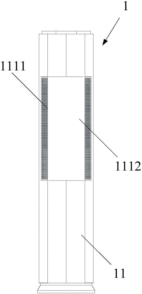
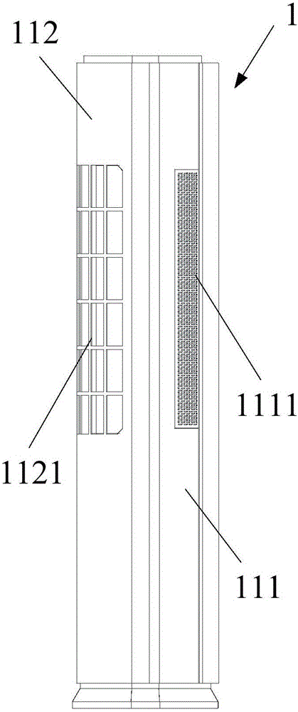
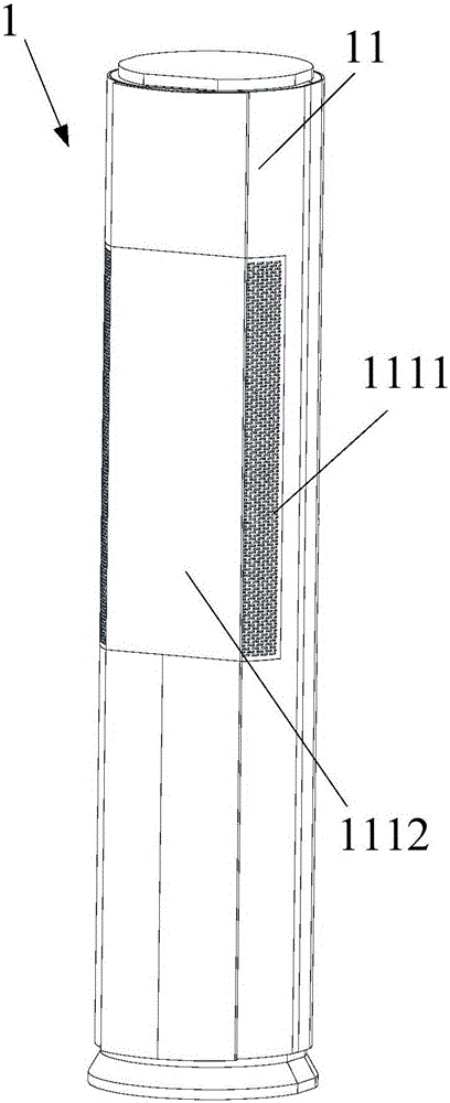
[0070] Such as figure 1 , 2 , 3, 4 and Figure 7 As shown, the indoor unit 1 of the air conditioner provided by the present invention includes a casing 11 and an air duct assembly 114 arranged in the casing 11. An air flow channel 1141 is formed in the air duct assembly 114. The casing 11 includes a front A panel 111 and a back panel 112 opposite to the front panel 111, the front panel 111 and the back panel 112 together form an accommodating space, the air duct assembly 114 and th...

Embodiment 2

[0088] Such as Figure 8 As shown, the technical solution in this embodiment is substantially the same as that in Embodiment 1, the main difference is that in this embodiment, the first air outlet 1111 (air outlet without wind sense) is provided and located on the front panel 111 The middle part of the second air outlet 1112 (that is, the conventional air outlet) is provided with two, and are respectively located on both sides of the first air outlet 1111, and the second air outlet 1112 and the first air outlet 1111 are located on the upper side of the front panel 111, and an air inlet 1121 is also provided on the upper side of the back panel 112; optionally, as Figure 4 , 5 As shown in and 8, the air conditioner indoor unit 1 is a circular cabinet, and the switching device includes a door panel 1115 arranged on the front panel 111 and a driving mechanism 115 for driving the door panel 1115 to move, and the door panel 1115 Driven by the driving mechanism 115, the second air...

Embodiment 3

[0093] Such as Figure 9 As shown, the technical solution in this embodiment is substantially the same as that in Embodiment 1, and the main difference is that, as Figure 9 and Figure 15 As shown, the switching device in this embodiment is the deflector 118 arranged in the casing 11, and the deflector 118 can control the flow between the first air outlet 1111 and the airflow channel 1141 and the flow between the second air outlet 1112 and the airflow channel 1141. The communication of the airflow channel 1141; specifically, such as Figure 9 As shown, the housing 11 is provided with a deflector 118 and a splitter 119, one end of the deflector 118 is close to the splitter 119, and two airflow passages 1141 are provided, and each airflow passage Cross-flow wind wheels 1144 are respectively provided in 1141, and two deflectors 118 are also provided, and are respectively located in the two air flow ducts; as Figure 4 and Figure 5 As shown, one end of the deflector 118 is r...


PUM


Abstract

The invention relates to the technical field of household appliances, in particular to a control method for an air conditioner indoor unit. The provided control method for the air conditioner indoor unit can select a conventional air out mode or a non-air-feel air out mode according to a control signal, thus, the air out mode of the air conditioner indoor unit is more diversified, and the user usage requirements can be met better; when a second air outlet conducts air exhaust, a conventional air blowing mode is achieved, and a first air outlet is in a closed state; when the first air outlet is switched to conduct air exhaust through a switching device, the second air outlet is closes and stops conducting air exhaust; due to the fact that the first air outlet is provided with an air deflector, a plurality of micropores are formed in the air deflector, and an air flow blown to the first air outlet through an air duct assembly is dispersed into a lot of fine filiform air in a spreading mode when passing through the micropores in the air deflector; and a user can feel coolness or warmness in a room without being directly blown by cold air or hot air, non-air-feel air supply can be achieved, the user feels more comfortable, and the user experience is better.

Description

technical field [0001] The invention relates to the technical field of household appliances, in particular to a method for controlling an indoor unit of an air conditioner. Background technique [0002] At present, air conditioners, as a household appliance, have been gradually applied to ordinary families. The air conditioner includes an indoor unit and an outdoor unit. In the existing indoor units of the air conditioner, cold air or hot air is blown outwards through the air outlet to provide cooling or heat to the room. , blowing to the indoor user will cause the user to feel too cold or overheated, and the user will feel uncomfortable, which will affect the user's experience. Contents of the invention [0003] (1) The technical problem to be solved by the present invention is: in the existing air-conditioning indoor unit, the temperature in the room is changed by directly blowing cold wind or hot wind into the room, but when the cold wind or hot wind blows directly on ...

Claims


Application Information

Patent Timeline
IPC IPC(8): F24F1/00F24F11/00F24F13/06
CPCF24F1/0003F24F11/30F24F11/62F24F11/65F24F13/06
Inventor 闫长林陈良锐
Owner WUHU MATY AIR CONDITIONING EQUIP CO LTD
Why Eureka
Try Eureka