A laser gyro ring resonator optical path collimation device and method

A ring resonator and laser gyro technology, applied in the laser field, can solve the problems of poor collimation effect and low efficiency of the optical path of the laser gyro ring resonator, and achieve improved laser gyro performance and product qualification rate, good collimation effect, The effect of simple system structure

Active Publication Date: 2019-03-19
XIAN FLIGHT SELF CONTROL INST OF AVIC
View PDF5 Cites 2 Cited by
  • Summary
  • Abstract
  • Description
  • Claims
  • Application Information

AI Technical Summary

Problems solved by technology

[0004] In order to solve the problems of poor collimation effect and low efficiency of the optical path of the laser gyro ring resonator in the prior art, the present invention provides a laser gyro ring resonator optical path collimation device

Method used


Image

  • A laser gyro ring resonator optical path collimation device and method
  • A laser gyro ring resonator optical path collimation device and method
  • A laser gyro ring resonator optical path collimation device and method

Examples


Embodiment Construction

[0029] The present invention will be further described below by means of specific embodiments:

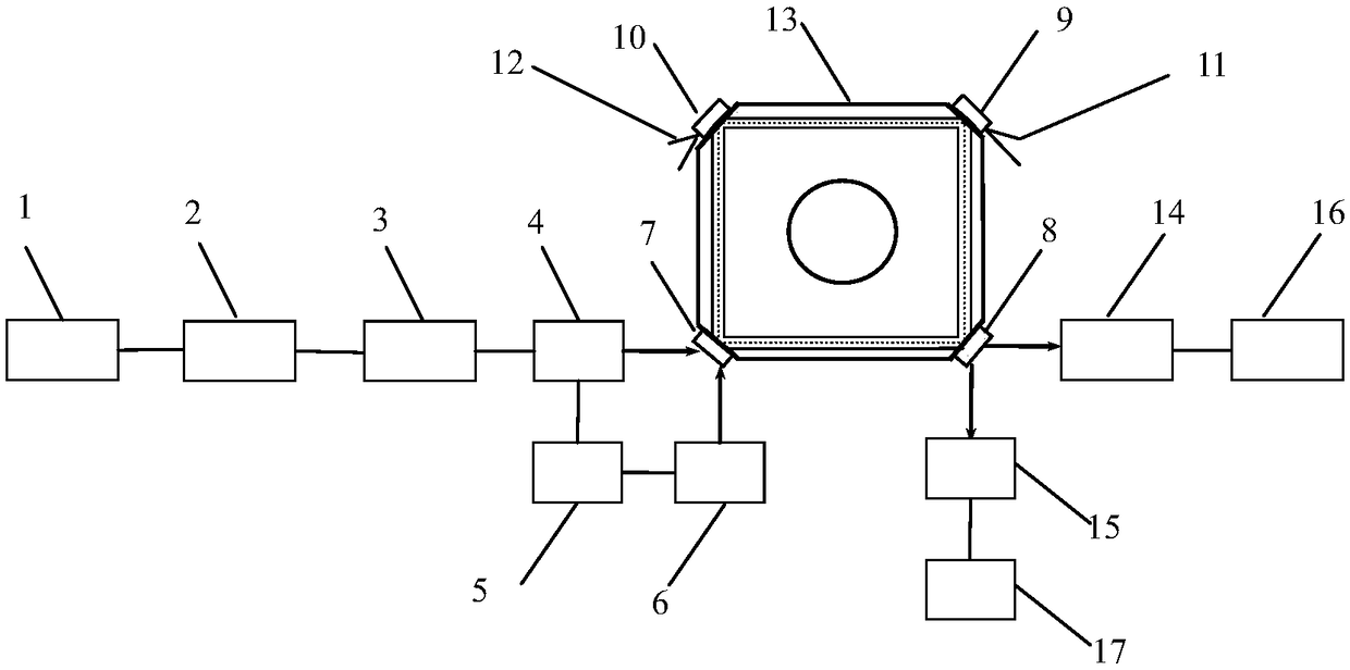
[0030] see figure 1 , which is a schematic diagram of a preferred embodiment of the laser gyro resonator optical path collimation device of the present invention. In this embodiment, the laser gyro resonator optical path collimation device includes a first plane mirror 7 and a second plane mirror 8, a first spherical mirror 9 and a second spherical mirror 10, a first tuning tool 11 and a second tuning tool 12, A cavity 13, two input optical paths and two receiving optical paths, wherein the first plane mirror 7 and the second plane mirror 8 are respectively arranged at the input end and the output end of the cavity body, the first tuning tool 11 and the second tuning tool 12 Set at the two adjustment ends of the cavity 13, the first spherical mirror 9 and the second spherical mirror 10 are respectively set on the first tuning tool 11 and the second tuning tool 12, and the two inpu...


PUM

PropertyMeasurementUnit
wavelengthaaaaaaaaaa
reflectanceaaaaaaaaaa

Abstract

The invention belongs to laser technology, and relates to a laser gyroscope annular resonant cavity light path alignment device and method. The laser gyroscope annular resonant cavity light path alignment device comprises a laser device, a light path adjusting component, polarizers, a half transparent and half reflecting mirror, high-reflectivity mirrors, plane mirrors, spherical mirrors, cavity adjusting tools and photoelectric receivers, wherein light output by the laser device enters the polarizers and the half transparent and half reflecting mirror after being adjusted through a light beam adjusting mechanism, then one path of light is directly injected into an annular resonant cavity in the horizontal direction, and the other path of light is reflected by the high-reflectivity mirrors and then is injected into the resonant cavity in the vertical direction. The photoelectric receivers are connected with the resonant cavity through the polarizers and used for detecting output light in the horizontal and vertical direction respectively. The spherical mirrors are dynamically adjusted in real time according to characteristics of linearly polarized light received by the two receiving light paths, annular resonant cavity light path alignment is completed until extinction coefficients of polarized light clockwise and counter-clockwise paths are equal, and tiny non-coplanar light path compensation of the annular resonant cavity is achieved.

Description

technical field [0001] The invention belongs to laser technology, in particular to a method and device for collimating the optical path of a laser gyroscope ring resonant cavity. Background technique [0002] The ring resonator is the core device of the laser gyroscope, which plays a decisive role in the performance of the laser gyroscope. Due to the machining error of each reflective surface, the machining error of the cavity, and the lateral angle deformation error of each lens, the ring resonator will cause a non-coplanar error in the ring-shaped closed optical path of the resonator, thereby forming a slightly non-coplanar cavity. This results in a large magnetic zero bias of the ring laser gyro, which seriously affects the accuracy of the ring laser. [0003] The existing optical path collimation method generally needs to monitor the two outgoing spots of the ring laser at the same time, and adjust the optical path of the cavity according to its position information. T...

Claims


Application Information

Patent Timeline
Patent Type & Authority Patents(China)
IPC IPC(8): G01C19/72
CPCG01C19/721
Inventor 王朋国李县洛
Owner XIAN FLIGHT SELF CONTROL INST OF AVIC
Why Eureka
Try Eureka