
Low error-sensitivity multi-target light source-mask optimization method based on vector imaging model

An imaging model and sensitivity technology, applied in optics, optomechanical equipment, microlithography exposure equipment, etc., can solve the problem of random errors that cannot be compensated for other wave aberrations, imaging light wave intensity or phase changes, affecting imaging resolution and preservation. Fidelity and other issues, to achieve good lithography performance, reduce the impact of lithography imaging, and achieve the effect of high graphic fidelity

Active Publication Date: 2017-11-21
BEIJING INSTITUTE OF TECHNOLOGYGY
View PDF10 Cites 4 Cited by
  • Summary
  • Abstract
  • Description
  • Claims
  • Application Information

AI Technical Summary

Problems solved by technology

However, the above method has the following three shortcomings: first, this method is based on a scalar imaging model, which does not take into account the polarization effect of light, and cannot accurately describe the propagation, focusing and imaging process of light in the case of immersion lithography with a large NA; second, the method The method only targets the low-order spherical aberration caused by the topological effect of the mask, and cannot compensate other wave aberrations and other random errors; finally, the method does not control the sensitivity of the imaging results to errors, which makes the method less sensitive to extreme errors. Insufficient compensation ability
The above errors will cause changes in the intensity or phase of the imaging light wave, which will affect the imaging resolution and fidelity

Method used


Image

  • Low error-sensitivity multi-target light source-mask optimization method based on vector imaging model
  • Low error-sensitivity multi-target light source-mask optimization method based on vector imaging model
  • Low error-sensitivity multi-target light source-mask optimization method based on vector imaging model

Examples


Embodiment

[0096] Now assume that the random error in the lithography system is only the eighth Zernike polynomial z 8 The wave aberration represented by z 8 The coefficient c of the term 8 can represent the error of the system.

[0097] Such as image 3 Shown is a schematic of the initial light source, the initial mask and its corresponding imaging in the photoresist. exist image 3 Among them, 301 is the pattern of the preliminary test light source, white represents the luminous part, and black represents the non-luminous part. 302 is the initial test mask pattern, which is also the target pattern, white represents the light-transmitting area, black represents the light-blocking area, and its characteristic size is 45nm. in c 8 In the case of = 0, 303 is after adopting 301 as the light source and 302 as the mask, imaging in the photoresist of the photolithography system, and its graphic error is 7224 (the imaging fidelity function F is defined here as the value of the graphic err...


PUM

PropertyMeasurementUnit
optical propertiesaaaaaaaaaa

Abstract

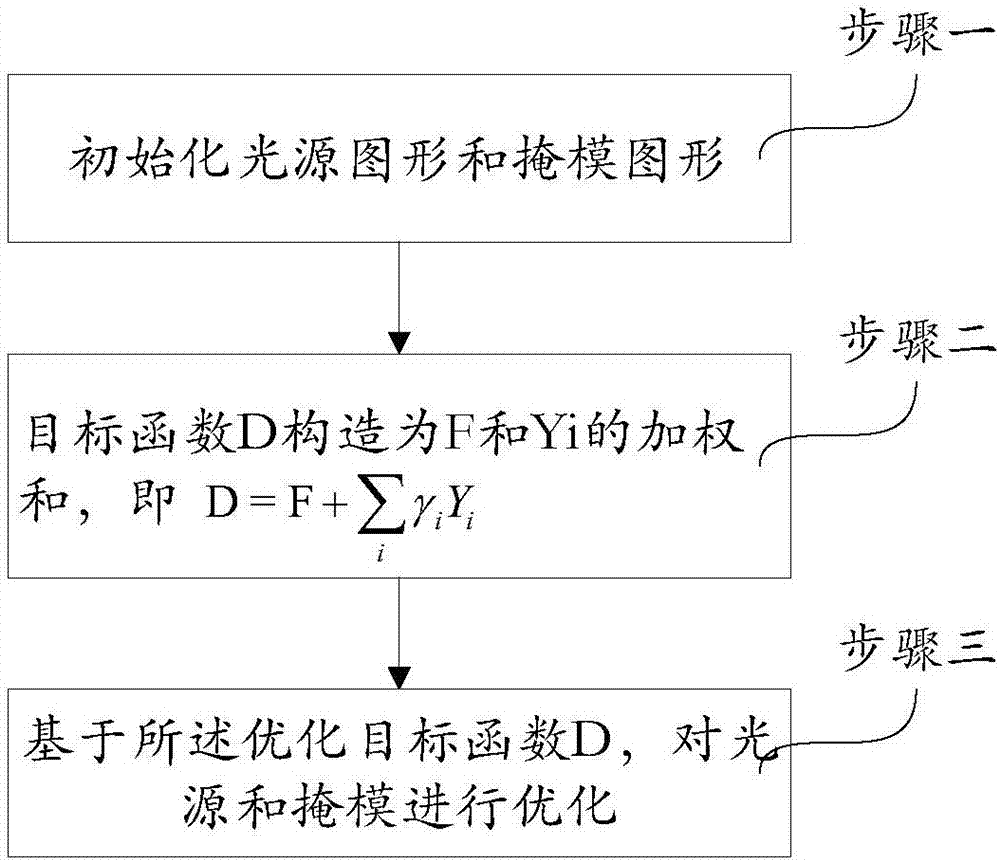
The invention provides a vector imaging model-based low-error sensitivity multi-objective light source-mask optimization method. The method comprises the processes as follows: a light source pattern and a mask pattern are initialized; F is set to be an imaging fidelity function as shown in the specification; the formula as shown in the specification is pixel values of various pixel points of an objective pattern; Z(x, y) represents the pixel vales, calculated by a vector imaging model, of the pixel points for imaging in a photoresist corresponding to the current light source pattern and mask pattern; a sensitivity penalty function of an imaging result to an error is constructed as shown in the specification; I(x, y) is the pixel values, calculated by the vector imaging model, of the pixel points of an aerial image corresponding to the current light source pattern and mask pattern; ei represents an error factor; an objective function D is constructed as weighted sum, as shown in the specification, of F and Yi, and gammai is a weight coefficient; and a light source and a mask are optimized on the basis of the optimized objective function D. The optimized light source and mask are within a certain error range through the optimized objective function; and a relatively good exposure effect can be obtained.

Description

technical field [0001] The invention relates to a low-error-sensitivity multi-target light source-mask optimization method based on a vector imaging model, and belongs to the technical fields of resolution enhancement such as integrated circuit design, manufacturing equipment, technology, microscopic imaging, and telephoto imaging. Background technique [0002] Photolithography is the core process in the VLSI manufacturing field. At present, the operating wavelength of the mainstream lithography system in the industry is 193nm. As the lithography process enters the technology node of 45-14nm and below, the critical dimension of the integrated circuit has been far smaller than the wavelength of the light source. Therefore, the vector light field effect and complex light diffraction lead to distortion, shift or resolution reduction of lithography imaging; for this reason, the lithography system must adopt resolution enhancement technology at this time to improve the quality of...

Claims


Application Information

Patent Timeline
Patent Type & Authority Patents(China)
IPC IPC(8): G03F7/20
CPCG03F7/70058
Inventor 李艳秋李铁
Owner BEIJING INSTITUTE OF TECHNOLOGYGY
Learn More