
Shift register unit and grid scanning circuit

A technology of shift register and scanning pulse, which is applied in the field of gate scanning circuit and shift register unit, which can solve the problems of single display mode, inability to meet display requirements, poor flexibility, etc., and achieve the effect of improving flexibility

Active Publication Date: 2016-11-16
BOE TECH GRP CO LTD +1
View PDF5 Cites 19 Cited by
  • Summary
  • Abstract
  • Description
  • Claims
  • Application Information

AI Technical Summary

Problems solved by technology

[0005] An object of the present invention is to provide a new type of shift register unit, which is used to solve the problem that the existing gate drive circuit including the shift register unit adopts a forward progressive scanning mode for scanning the gate lines, so that the display mode Relatively single, poor flexibility, unable to meet the display requirements of various states

Method used

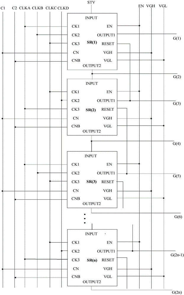
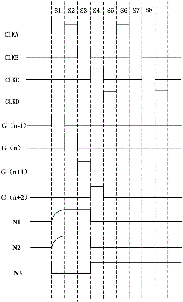

Image

  • Shift register unit and grid scanning circuit
  • Shift register unit and grid scanning circuit
  • Shift register unit and grid scanning circuit

Examples


Embodiment Construction

[0050] In order to understand the above-mentioned purpose, features and advantages of the present invention more clearly, the present invention will be further described in detail below in conjunction with the accompanying drawings and specific embodiments. It should be noted that, in the case of no conflict, the embodiments of the present application and the features in the embodiments can be combined with each other.

[0051] In the following description, many specific details are set forth in order to fully understand the present invention. However, the present invention can also be implemented in other ways different from those described here. Therefore, the protection scope of the present invention is not limited by the specific details disclosed below. EXAMPLE LIMITATIONS.

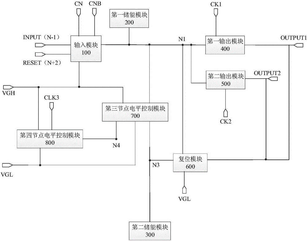
[0052] In a first aspect, the present invention provides a shift register unit, see figure 1 ,include:

[0053] The input module 100 is connected to the first DC voltage terminal CN, the second DC ...


PUM


Abstract

The invention provides a shift register unit and a grid scanning circuit. In the shift register unit, the voltage of a first node is increased through a first DC voltage end when a first scanning pulse input end is at a first level; the voltage of the first node is increased through a second DC voltage end when a second scanning pulse input end is at the first level, thereby achieving the reverse scanning and enabling a shift register provided by the invention to be able to support the bidirectional scanning of a grid line. In addition, the shifting register unit at each stage is provided with two scanning pulse output ends. The second scanning pulse output end can output a grid voltage to the pixel units in an (N+1)-th row at a next time stage of the moment when the first scanning pulse output end outputs a grid drive signal to an N-th stage pixel unit, thereby achieving a purpose that the shift register at the same stage controls starting of pixels in two rows, effectively improving the display flexibility, and meeting the display demands of different states.

Description

technical field [0001] The invention relates to the field of display technology, in particular to a shift register unit and a gate scanning circuit. Background technique [0002] GOA (Gate Driver On Array, the gate driver circuit is integrated on the array substrate) is an important means to realize the narrowing of the display device. Generally, the gate drive circuit integrated on the array substrate is composed of multi-level shift register units, and each level of shift register units sequentially shifts and outputs a scan pulse to the gates of the thin film transistors in the pixel units of each row, The corresponding thin film transistors are turned on, so as to realize the driving process of the pixel units in each row. [0003] The shift register unit in the gate drive circuit commonly used in the prior art is mainly composed of thin film transistors and capacitors. For each stage of shift register unit, its current output scan pulse output(n) is used as the next st...

Claims


Application Information

Patent Timeline
IPC IPC(8): G09G3/36G11C19/28
CPCG09G3/3677G11C19/28G09G2310/0286G09G3/3266G09G2310/0283G09G3/20G09G2300/0809G09G2310/08G11C19/287
Inventor 王继国李付强
Owner BOE TECH GRP CO LTD
Learn More