Bidirectional scanning control switch, grid drive circuit and working method

A technology for controlling switches and bidirectional scanning, which is applied in the field of gate drive circuits and bidirectional scanning switches, can solve the problems of poor display flexibility, failure to meet display requirements, and single display mode, and achieve simple structure, flexible display mode, and satisfying display requirements. effect of demand

Active Publication Date: 2014-05-21
BOE TECH GRP CO LTD +1
View PDF5 Cites 0 Cited by
  • Summary
  • Abstract
  • Description
  • Claims
  • Application Information

AI Technical Summary

Problems solved by technology

[0010] The embodiment of the present invention discloses a bidirectional scanning control switch, a gate drive circuit and a working method, which are used to solve the problem that the display points of the liquid crystal units in the TFT panel are sequentially lit up from top to bottom by the traditional gate drive circuit. The method is relatively single, the display flexibility is poor, and it cannot meet the display requirements of various states

Method used


Image

  • Bidirectional scanning control switch, grid drive circuit and working method
  • Bidirectional scanning control switch, grid drive circuit and working method
  • Bidirectional scanning control switch, grid drive circuit and working method

Examples


Embodiment 1

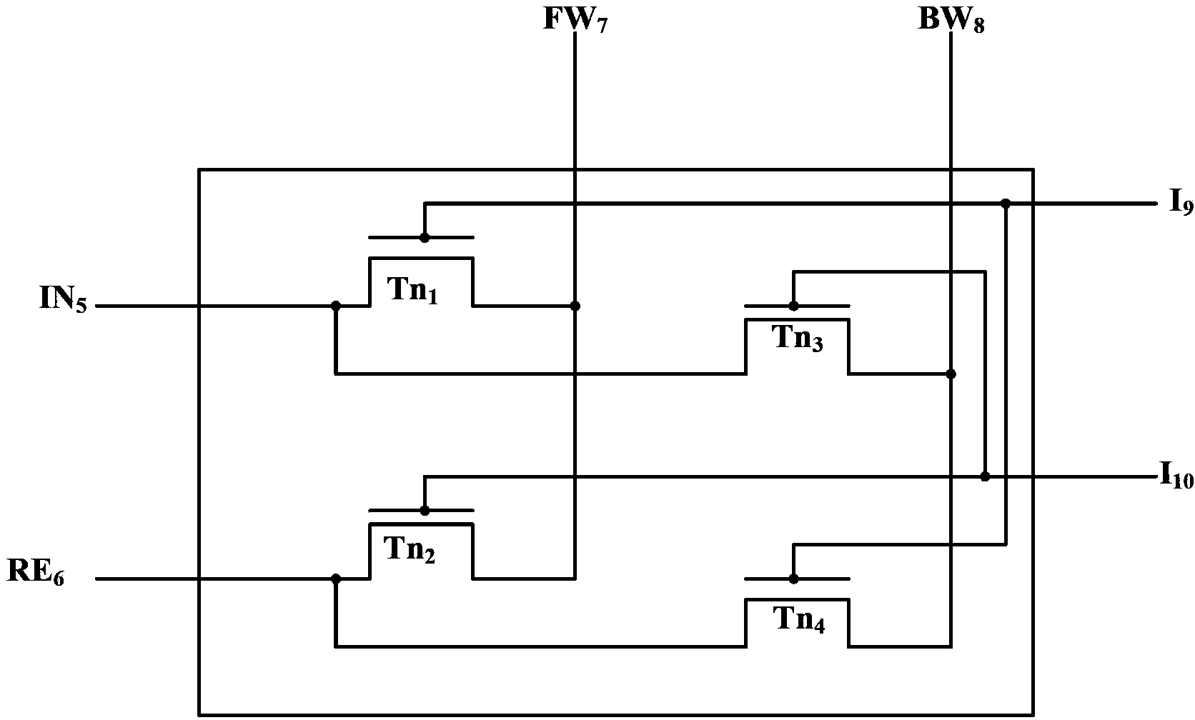
[0043] Such as figure 2 As shown, it is a schematic structural diagram of a bidirectional scanning control switch in Embodiment 1 of the present invention. The bidirectional scanning control switch includes: forward scanning control voltage port FW 7 , Reverse scan control voltage port BW 8 , the first input port I 9 , the second input port I 10 , the first output port IN 5 , the second output port RE 6 , the first transistor Tn 1 , the second transistor Tn 2 , the third transistor Tn 3 and the fourth transistor Tn 4 ,in:

[0044] first transistor Tn 1 The gate of the first input port I 9 connected, the first transistor Tn 1 The drain of the positive scan control voltage port FW 7 connected, the third transistor Tn 3 The gate of the second input port I 10 connected, the third transistor Tn 3 The drain of the reverse scan control voltage port BW 8 connected, the third transistor Tn 3 source of the first transistor Tn 1 The connection point where the source i...

Embodiment 2

[0056] Such as Figure 4 Shown is a flow chart of a working method of a bidirectional scanning control switch. In the second embodiment, a bidirectional scanning control switch with 4 transistors is taken as an example for illustration. The working method of the bidirectional scanning control switch is:

[0057] Step 101: Scan the control voltage port FW in the forward direction 7 Input high level, then execute step 102; In reverse scanning control voltage port BW 8 If a high level is input, step 105 is executed.

[0058] Step 102: At the first input port I 9 Input high level, then execute step 103; In the second input port 1 10 If a high level is input, step 104 is executed.

[0059] Step 103: first transistor Tn 1 is in the conduction state through the first transistor Tn with 1 The source is connected to the first output port IN 5 output high level.

[0060] Step 104: the second transistor Tn 2 is in the conduction state through the second transistor Tn with 2 T...

Embodiment 3

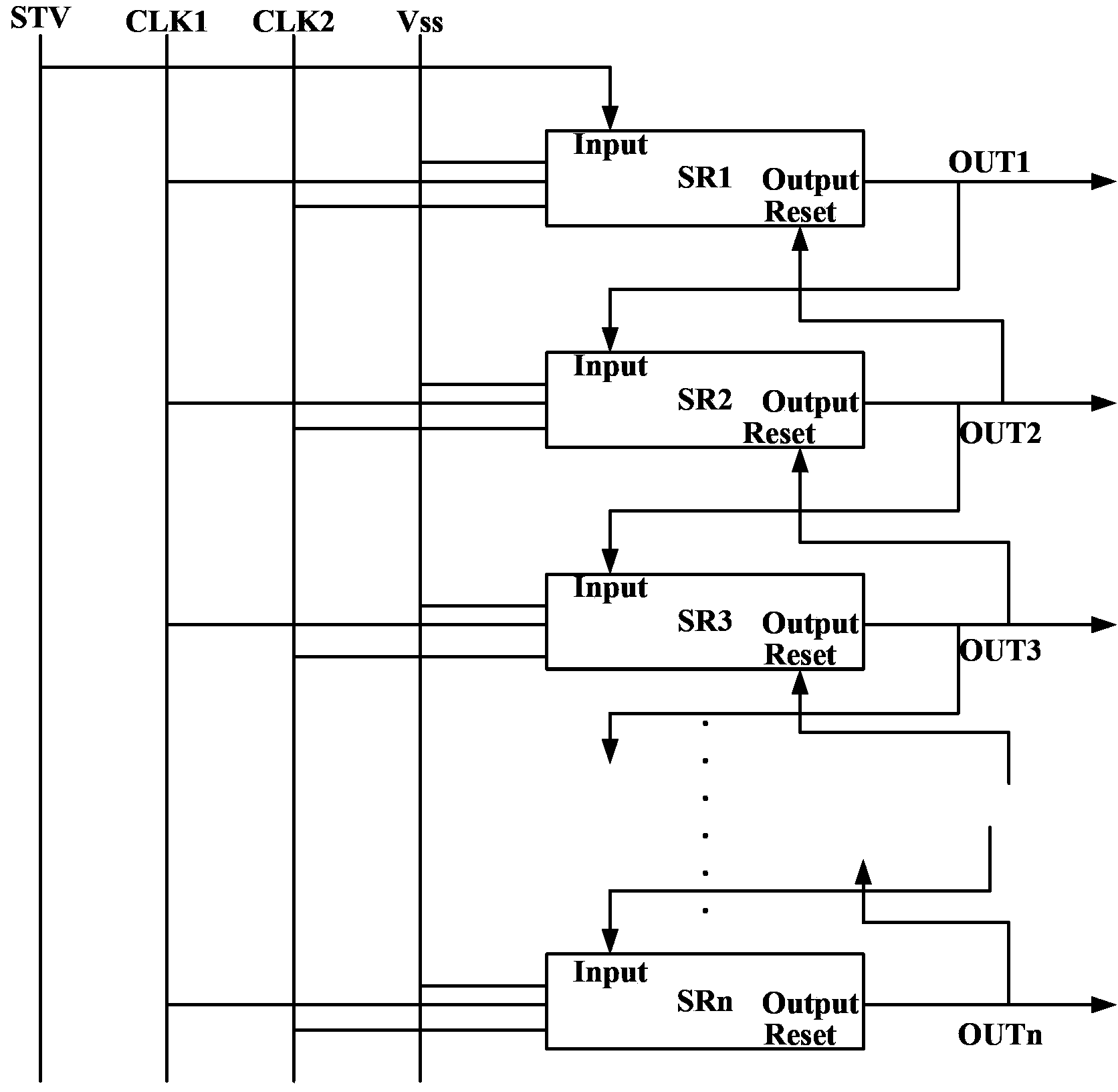
[0065] Such as Figure 5 Shown is a schematic structural diagram of a gate driving circuit in the third embodiment. The gate drive circuit also includes: a turn-on pulse STV supply line STV 13 , Forward scanning provides line L 14 , Reverse scanning provides line L 15 , n shift registers SR 1 ~SR n , n bidirectional scanning control switches CS 1 ~CS n , at least two switch units, the n is a positive integer, wherein:

[0066] Forward scan control voltage port FW in each bidirectional scan control switch 7 with a forward scan providing the line L 14 Connected, reverse scan control voltage port BW 8 with a reverse scan providing the line L 15 connected;

[0067] Turn on pulse STV supply line STV 13 Connected to the gate of a switching unit whose source is connected to the first bidirectional scan control switch CS 1 The first input port in I 9 Connected, the drain of the switching unit is connected to the forward scan supply line L 14 connected;

[0068] The mth...


PUM


Abstract

The embodiment of the invention discloses a bidirectional scanning control switch, a grid drive circuit and a working method. The main content is as follows: a bidirectional scanning control switch is arranged, wherein after using the bidirectional scanning control switch in a gate drive circuit, a high level input from a voltage port is controlled by using a forward scan, the low level input from the voltage port is controlled by using a backward scan; the forward output gate drive signal can carry out the forward scan on a display point of a liquid crystal unit in a thin film transistor (TFT) panel; the high level input from the voltage port is controlled by using the backward scan, the low level input from the voltage port is controlled by using the forward scan, the backward output gate drive signal can carry out the backward scan on the display point of the liquid crystal unit in the TFT panel. The bidirectional scanning control switch can make the display method of the TFT panel flexible relatively.

Description

technical field [0001] The invention relates to the technical field of liquid crystal display, in particular to a bidirectional scanning switch, a gate drive circuit and a working method. Background technique [0002] Liquid crystal displays have been widely used in various display fields, such as LCD TVs for home use, liquid crystal display advertising boards for public places, computer liquid crystal displays for office use, and many electronic related products for personal use. A traditional liquid crystal display uses an electric field to control the light transmittance of the liquid crystal layer, and then displays images on the liquid crystal display panel. This liquid crystal display includes a liquid crystal display panel and a driving circuit, wherein the liquid crystal cells in the liquid crystal display panel are arranged in a matrix. [0003] Specifically, when the liquid crystal display is powered on for display, the drive circuit inside the liquid crystal displ...

Claims


Application Information

Patent Timeline
Patent Type & Authority Patents(China)
IPC IPC(8): G09G3/36
Inventor 谷晓芳邵贤杰马睿胡明
Owner BOE TECH GRP CO LTD
Why Eureka
Try Eureka