High-frequency sensitivity frequency scanning antenna

A sensitive, high-frequency technology, applied in the field of frequency scanning antenna arrays, it can solve the problems of large frequency range, frequency discontinuity, and increase of periodic structure attenuation constant, so as to achieve the effect of improving sensitivity and avoiding frequency discontinuity.

Inactive Publication Date: 2020-04-17
NANJING UNIV OF SCI & TECH
View PDF12 Cites 5 Cited by
  • Summary
  • Abstract
  • Description
  • Claims
  • Application Information

AI Technical Summary

Problems solved by technology

[0003] In the traditional sense, the leaky wave antenna introduces periodic units into its guided wave structure. When the scanning beam is close to the normal direction, the impedance mismatch will cause the reflected waves to continuously superimpose in phase, so that the attenuation constant of the periodic structure increases significantly. In this way, a stop band is formed, and only the backward to forward beam scanning in the direction of the division line can be realized, resulting in frequency discontinuity
For the leaky wave antenna, when a large scanning angle is required, a large frequency range is required, and the frequency sensitivity is very low

Method used


Image

  • High-frequency sensitivity frequency scanning antenna
  • High-frequency sensitivity frequency scanning antenna
  • High-frequency sensitivity frequency scanning antenna

Examples


Embodiment

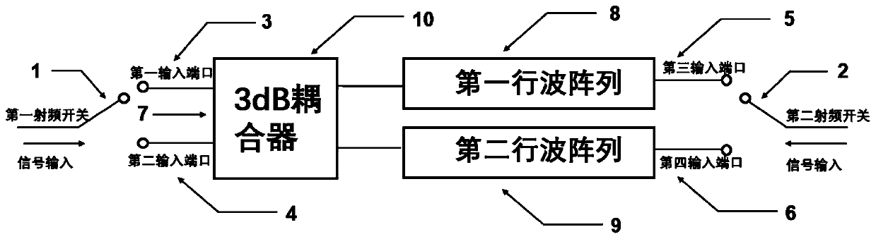
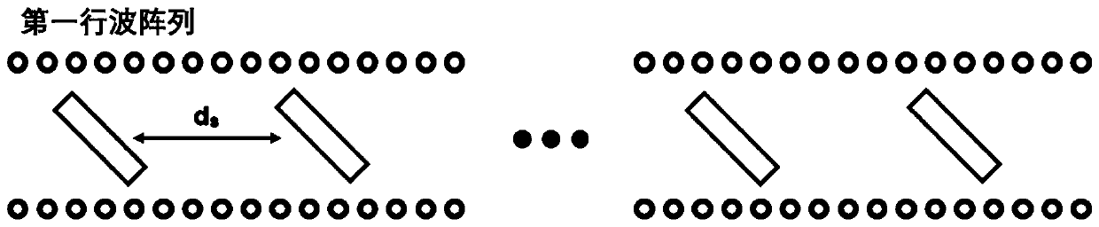
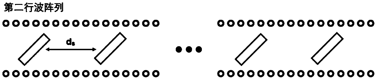
[0023] In order to verify the validity of the scheme of the present invention, the following simulation experiments are carried out, and the design center frequency is f 0 =36G, a frequency-swept antenna with a working frequency range of 33G-39G. The basic parameters of the antenna are selected as follows: the first traveling wave array 8 and the second traveling wave array 9 adopt substrate-integrated waveguide slot arrays, the radiation unit adopts elliptical slots, the number of array elements in the frequency-swept antenna is N=16, and the adjacent radiation cell spacing d s =λ / 2=5mm.

[0024] When the first RF switch 1 feeds power to the first input port 3, the obtained beam scanning range is as follows Figure 4 As shown, it can be seen from the figure that the range of scanning angles used by 33G to 39G is -25° to 0°. When the second RF switch 2 feeds power to the third input port 5, the resulting beam scanning range is as follows Figure 5 As shown, it can be seen ...


PUM


Abstract

The invention discloses a high-frequency sensitivity frequency scanning antenna which comprises a first radio frequency switch, a second radio frequency switch, a first input port, a second input port, a third input port, a fourth input port, a 3dB coupler and a frequency scanning antenna array. The frequency scanning antenna array comprises a first traveling wave array and a second traveling wavearray. A feed port is connected with the first input port and the second input port through the first radio frequency switch. The first input port and the second input port are connected with the input end of the 3dB coupler; the two output ends of the 3dB coupler are respectively connected with the first traveling wave array and the second traveling wave array, the other end of the first traveling wave array and the other end of the second traveling wave array are respectively connected with the third input port and the fourth input port, and the third input port and the fourth input port are connected with the feed port through the second radio frequency switch.

Description

technical field [0001] The invention belongs to a frequency scanning antenna array, in particular to a frequency scanning antenna with low loss and high frequency sensitivity. Background technique [0002] At present, electronic scanning antenna overcomes the slow scanning speed of traditional mechanical scanning, and has been widely used in military and civilian fields such as radar, communication, mobile TV, etc., and has been developed rapidly. As a kind of electrical scanning antenna, the frequency scanning antenna has attracted attention because of its simple structure, high reliability and low implementation cost. Leaky wave antenna is a relatively common frequency scanning antenna, which belongs to traveling wave antenna and has good frequency scanning characteristics and directivity. [0003] In the traditional sense, the leaky wave antenna introduces periodic units into its guided wave structure. When the scanning beam is close to the normal direction, the impedanc...

Claims


Application Information

Patent Timeline
IPC IPC(8): H01Q21/29H01Q21/08H01Q3/24H01Q3/22H01Q13/20
CPCH01Q3/22H01Q3/247H01Q13/20H01Q21/08H01Q21/29
Inventor 王森胥旺曹小芝戴永胜
Owner NANJING UNIV OF SCI & TECH
Why Eureka
Try Eureka