Time-lapse shooting method and mobile terminal
A mobile terminal, time-lapse photography technology, applied in the field of communications, can solve problems such as poor time-lapse photography effect
- Summary
- Abstract
- Description
- Claims
- Application Information
AI Technical Summary
Problems solved by technology
Method used
Image
Examples
no. 1 example
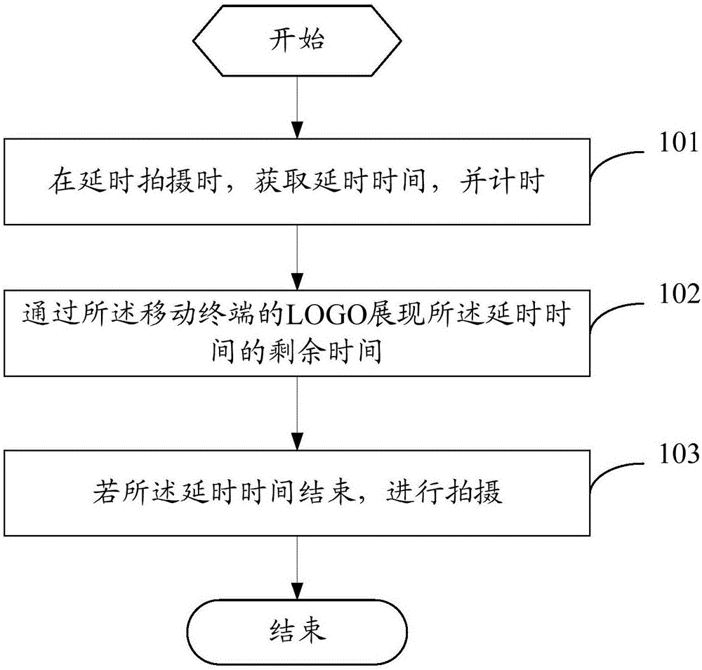
[0025] see figure 1 , figure 1 It is a flow chart of a time-lapse shooting method provided by an embodiment of the present invention, the method is applicable to mobile terminals, such as figure 1 shown, including the following steps:
[0026] Step 101 , during time-lapse shooting, acquire the time-lapse time and count it.
[0027] In this step, when the user clicks the delay shooting button, the delay time is acquired and timed. Wherein, the delay time may be preset, or set by the factory of the mobile terminal, or set by the user, and so on. Wherein, the timing here can be a countdown, for example, if the delay time is 5 seconds, then the countdown can start from 5, and when it reaches 0, it means that the delay time ends. Or the timing here can be countdown, for example, if the delay time is 5 seconds, then the timing can start from 0, and when it reaches 5 seconds, it means that the delay time is over.
[0028] Step 102, displaying the remaining time of the delay time...
no. 2 example
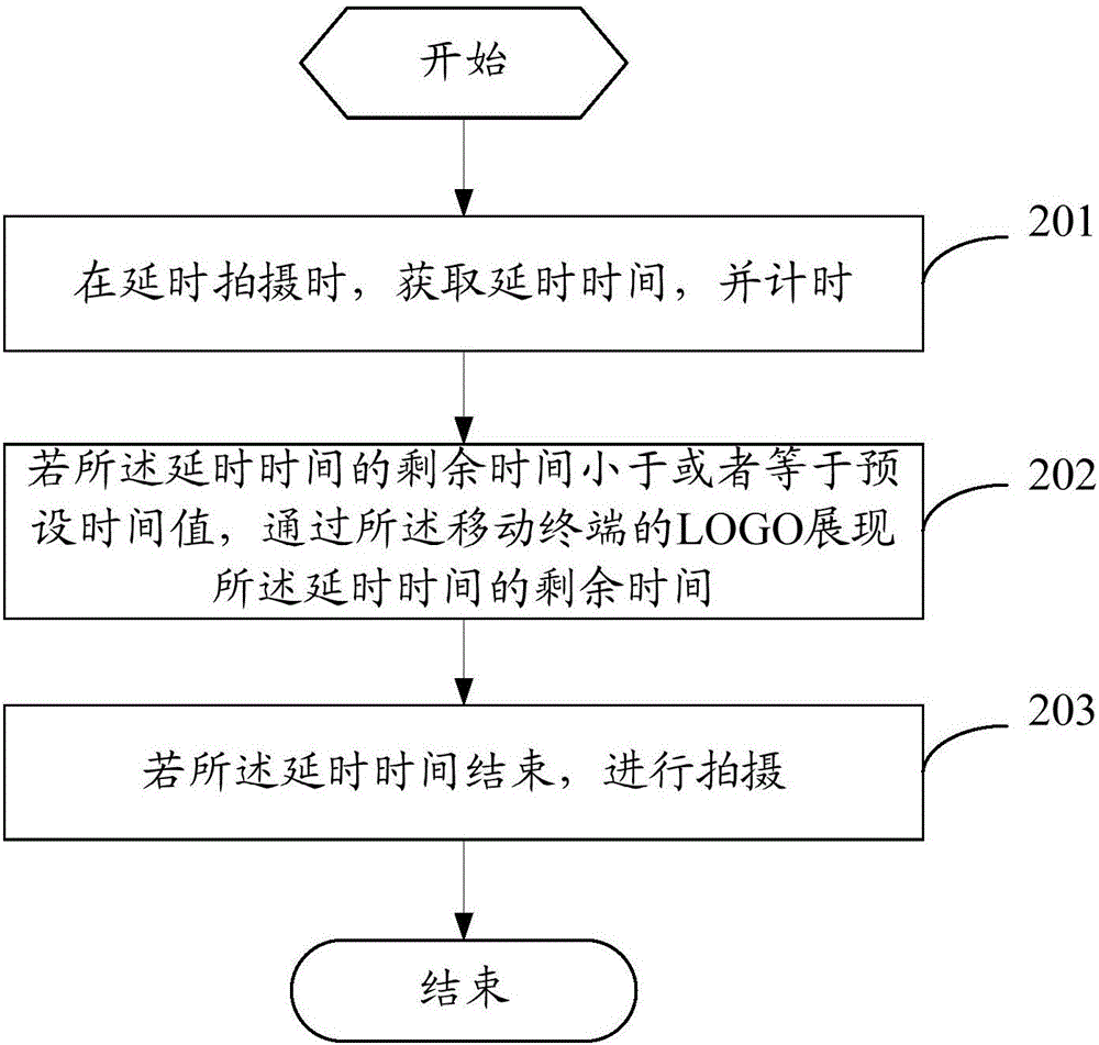
[0038] see figure 2 , figure 2 is a flow chart of another time-lapse shooting method provided by an embodiment of the present invention, the method is applied to a mobile terminal, such as figure 2 shown, including the following steps:
[0039] Step 201 , during time-lapse shooting, acquire the time-lapse time and count it.
[0040] Step 202: If the remaining time of the delay time is less than or equal to a preset time value, display the remaining time of the delay time through the LOGO of the mobile terminal.
[0041] In this step, it may be understood that the remaining time of the delay time is the preset time value, and the remaining time before shooting is the above-mentioned preset time value. For example: the above preset time value is 3 seconds, that is, when the remaining time before shooting is 3 seconds, the remaining time of the delay time is displayed through the LOGO of the mobile terminal. In this way, only when the remaining time from shooting is the ab...
no. 3 example
[0066] see Figure 7 , Figure 7 is a structural diagram of a mobile terminal provided by the implementation of the present invention, such as Figure 7 As shown, the mobile terminal 700 includes:
[0067] Timing module 701, used for obtaining the delay time and counting the time when delay shooting;
[0068] A presentation module 702, configured to present the remaining time of the delay time through the logo (LOGO) of the mobile terminal;
[0069] A photographing module 703, configured to photograph when the delay time is over.
[0070] Optionally, the presentation module 702 is configured to display the remaining time of the delay time through the LOGO of the mobile terminal if the remaining time of the delay time is less than or equal to a preset time value.
[0071] Optionally, the presentation module 702 is configured to control the characters corresponding to the remaining time of the delay time in the LOGO of the mobile terminal to emit light, wherein different rem...
PUM
 Abstract
Description
Claims
Application Information
 - R&D
- Intellectual Property
- Life Sciences
- Materials
- Tech Scout
- Unparalleled Data Quality
- Higher Quality Content
- 60% Fewer Hallucinations
Browse by: Latest US Patents, China's latest patents, Technical Efficacy Thesaurus, Application Domain, Technology Topic, Popular Technical Reports.
© 2025 PatSnap. All rights reserved.Legal|Privacy policy|Modern Slavery Act Transparency Statement|Sitemap|About US| Contact US: help@patsnap.com


