Rocking chair

A rocking chair and support frame technology, applied in the field of rocking chairs, can solve the problems that the rocking chair frame cannot be combined with dining chairs and trolleys, the assembly and disassembly process of the rocking chair is not convenient enough, and the baby falls to the ground, etc., to achieve soft rocking, easy folding, and less The effect of drop

Inactive Publication Date: 2016-11-23
ZHONGSAN CITY TOGYINBABY CO LTD
View PDF1 Cites 5 Cited by
  • Summary
  • Abstract
  • Description
  • Claims
  • Application Information

AI Technical Summary

Problems solved by technology

The rocking chair with this structure has the following disadvantages: 1. The first rotating shaft is the rotation center point of the entire seat frame during the swing process, and the third rotating shaft is the driving point for the seat frame to swing, that is, the driving point and the turning point of the seat frame These are two different points, so that when the rocking chair is used for a long time, if the first rotating shaft as the turning point fails, the turntable will still drive the driving rod to swing, and the driving rod will drive the seat frame through the third rotating shaft. In this way, when the first rotating shaft fails, the seat frame is still driven to swing, which is easy to cause the baby in the seat frame to fall to the ground, and the rocking chair has a safety hazard
2. The front end of

Method used


Image

  • Rocking chair
  • Rocking chair
  • Rocking chair

Examples


Embodiment 1

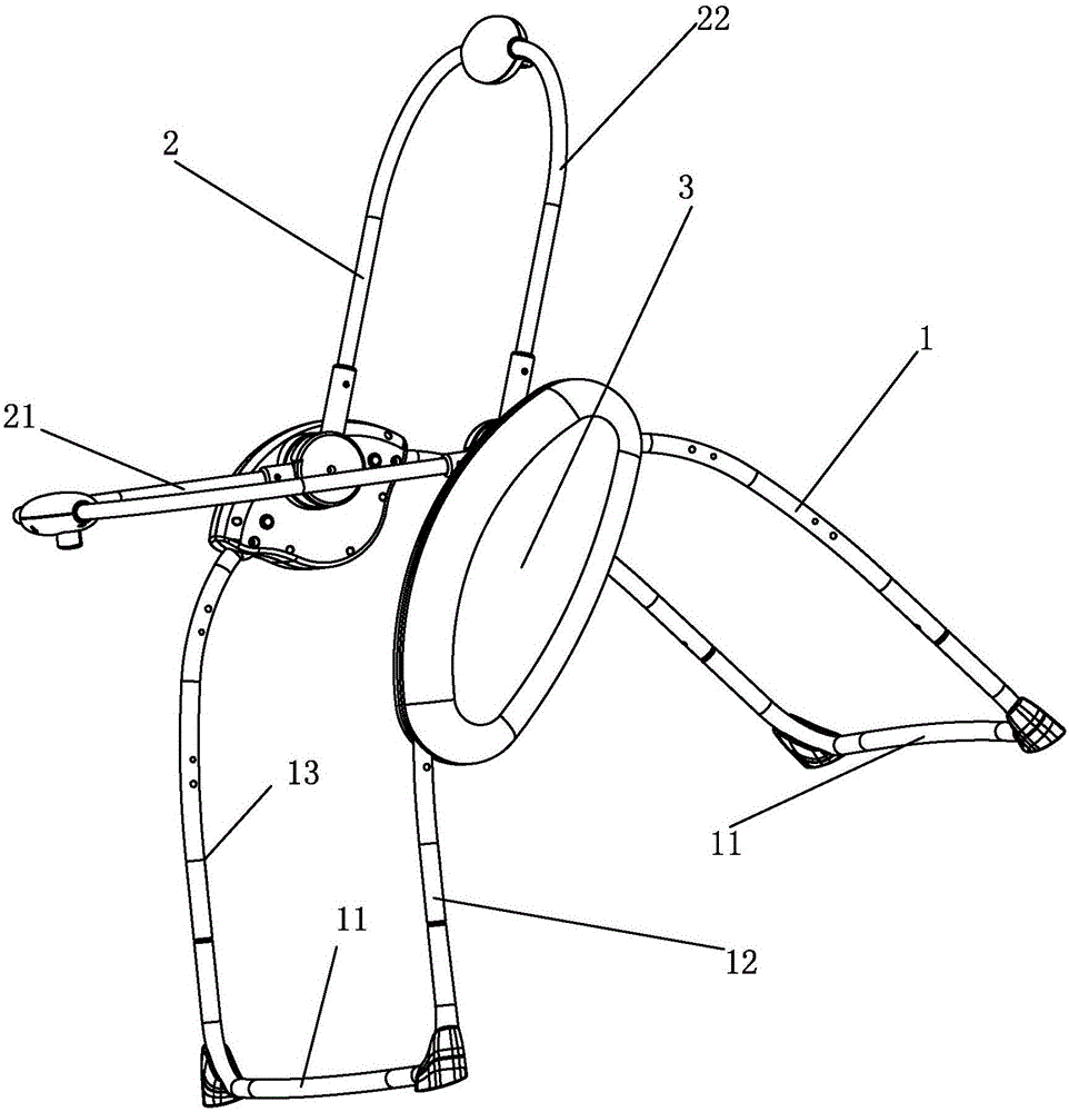
[0035] see Figure 1-6 , the support frame 1 includes a bottom frame 11 and a left side frame 12 and a right side frame 13 arranged thereon, and the seat frame 2 is arranged above the bottom frame 11 and between the left side frame 12 and the right side frame 13 Between, the installation shell 3 is fixed on the left side frame 12 or the right side frame 13 .

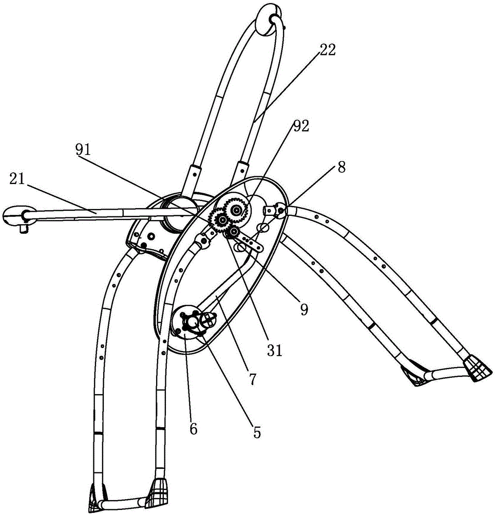
[0036] The other end of the swing member 8 is provided with a drive reduction gear set. The driving reduction gear set includes a driving gear 9 arranged at the other end of the swing member 8, the driving gear 9 is connected with a first-stage reduction gear 91, and the output end of the first-stage reduction gear 91 is connected with a second-stage reduction gear 92 , the shaft center of the second-stage reduction gear 92 is fixed with the rotating shaft 4 . By arranging the drive reduction gear set, the drop feeling of the driving mechanism can be reduced when there is a drop in the upper and lower heights, and the ...

Embodiment 2

[0043] see Figure 7 , the seat frame 2 includes a seat part 21 and a back part 22, the seat part and the back part are integrally formed, and the seat frame 2 is manufactured through integral processing of a mould, and its shape is pot-shaped. Others are the same as in Example 1.

Embodiment 3

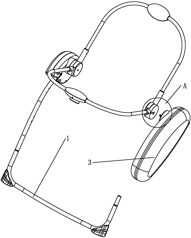
[0045] see Figure 8 , the support frame 1 only includes the left frame 1 or the right frame, the installation shell 3 is fixed on the left frame or the right frame, and the rotation axis 4 of the installation shell 3 is fixed at the approximate center of gravity of the seat frame 2 connect.


PUM


Abstract

The invention discloses a rocking chair. The rocking chair comprises a supporting frame and a seat frame which is arranged on the supporting frame and provided with a seat. An installing shell is arranged on the supporting frame, a driving motor is further arranged in the installing shell, a rotating piece is fixedly connected on an output shaft of the driving motor, a driving piece is pivoted on the rotating piece, a pivoting point between the driving piece and the rotating piece deviates the rotating shaft center of the rotating piece, a swinging piece is pivoted to the other end of the driving piece, a swinging-piece pivoting part is arranged on the installing shell, the other end of the swinging piece is pivoted with the swinging-piece pivoting part, a rotating shaft which rotates along with swinging of the other end of the swinging piece and is used for a supporting piece is further connected to the other end of the swinging piece, and is fixedly connected with the general gravity center of the seat frame. By means of the rocking chair, the defects of the technology are overcome, and the rocking chair which is simple in structure, coincident in driving point and rotating point, safe and reliable is provided.

Description

[technical field] [0001] The invention relates to a rocking chair. [Background technique] [0002] Existing rocking chairs generally include a support frame and a seat frame that is arranged on the support frame and can swing back and forth relative to it. However, the driving structure for driving the swing of the seat frame relative to the support frame is relatively complicated. The publication number is CN201585742U, and the name is a utility model patent for a baby rocking chair. The driving structure is relatively simple, and it includes a rocking chair support frame and a seat frame. The front part is rotatably connected with the drive rod through the third rotating shaft, and the other end of the drive rod is eccentrically rotatably connected with the turntable. The rocking chair with this structure has the following disadvantages: 1. The first rotating shaft is the center of rotation of the entire seat frame during the swing process, and the third rotating shaft i...

Claims


Application Information

Patent Timeline
IPC IPC(8): A47D13/10
CPCA47D13/105A47D9/057A47D9/016A47D1/06A47D9/005A47D1/10A47D13/101
Inventor 刘韦兵
Owner ZHONGSAN CITY TOGYINBABY CO LTD
Why Eureka
Try Eureka