IGBT aging state detection system

A detection system and aging state technology, applied in the field of detection systems, can solve problems such as poor stability, high cost, and large-scale fluctuations, and achieve the effect of good stability and low cost

Active Publication Date: 2016-11-30
CHONGQING UNIV
View PDF2 Cites 15 Cited by
  • Summary
  • Abstract
  • Description
  • Claims
  • Application Information

AI Technical Summary

Problems solved by technology

[0003] During the working process of the IGBT, due to the long-term operating conditions of large-scale random fluctuations in power, the internal junction temperature of the IGBT device continues to fluctuate in a large range, which in turn causes the IGBT to age and fail. If the aging of the IGBT device cannot be detected in time state and replace the aging IGBT, which will cause heavy losses. The detection and judgment of the aging state of the IGBT is generally realized through the saturation voltage drop Vce between the collector and the emitter of the IGBT. In the prior art, the saturation conduction of the IGBT The current is injected when the IGBT is turned on, and then the saturation voltage drop Vce of the IGBT is measured. Therefore, the existing technology has the following disadvantages: in the measurement process, the data of one point is used as the aging parameter to judge the aging state of the IGBT, and the stability is poor. During the working process, it is difficult to accurately detect the collector current for each measurement. In order to ensure the collector current and the saturation voltage drop Vce of the collector and emitter, precision instruments must be used, resulting in high cost

Method used


Image

  • IGBT aging state detection system
  • IGBT aging state detection system
  • IGBT aging state detection system

Examples


Embodiment Construction

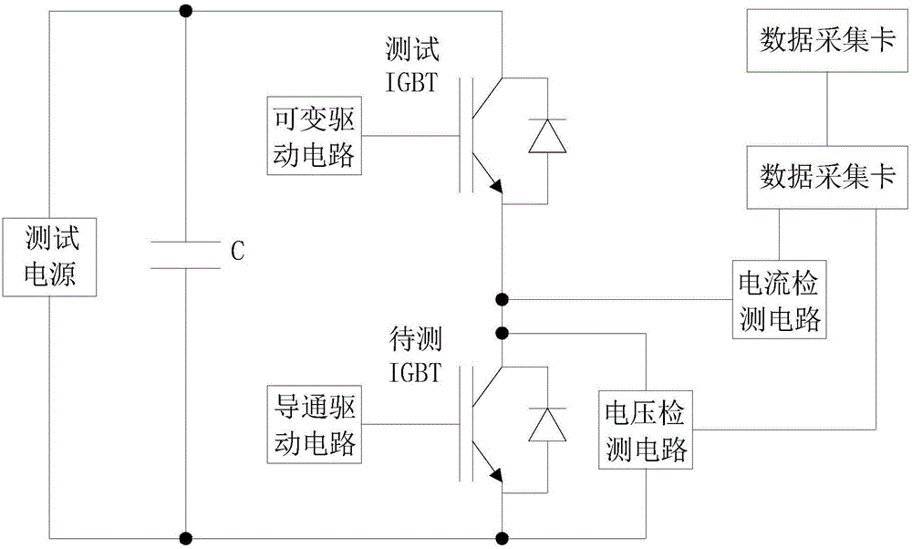
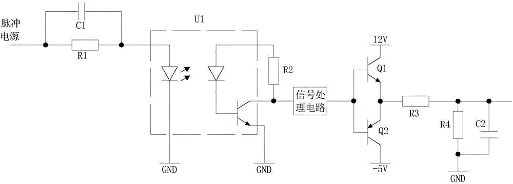
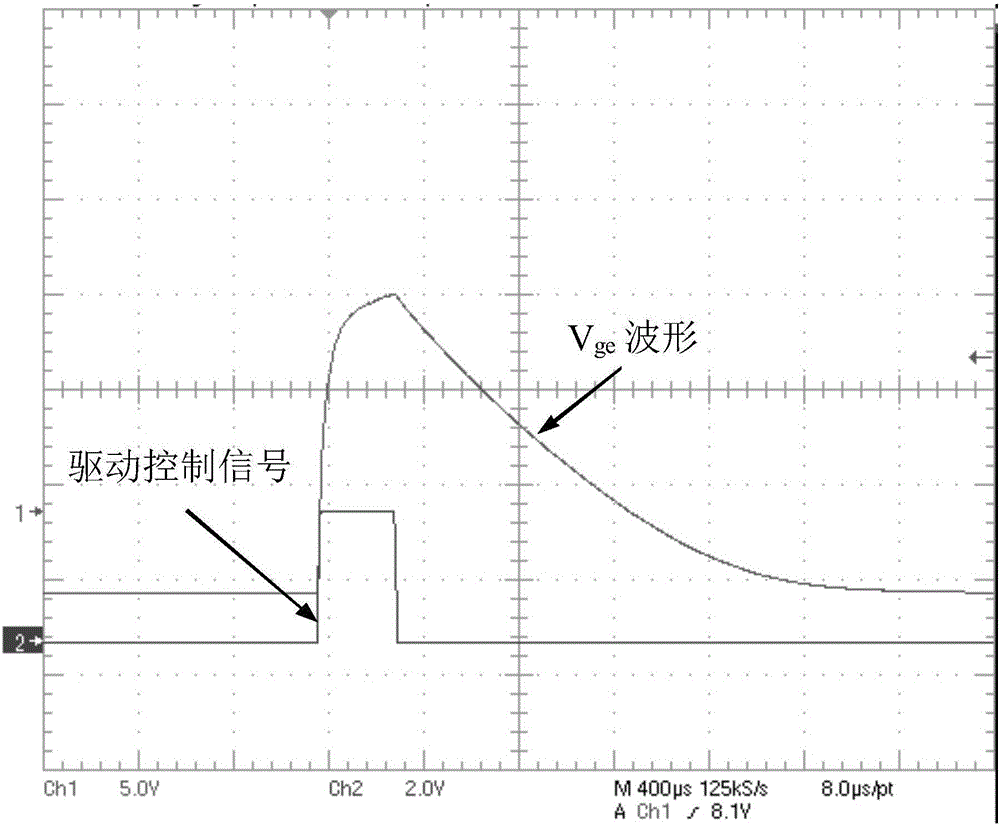
[0021] figure 1 It is a structural diagram of the present invention, figure 2 It is a schematic diagram of the variable drive circuit of the present invention, image 3 Output waveform diagram for the variable drive circuit of the present invention, Figure 4 For the measurement result waveform diagram of the present invention, Figure 5 It is a comparison chart of the IBGT characteristic curve to be tested in the present invention. As shown in the figure, a kind of IGBT aging state detection system provided by the present invention includes a test power supply, a test IGBT, a variable drive circuit that can output continuously changing currents, and a conduction drive. circuit, acquisition unit and host computer;

[0022] The emitter of the test IGBT is connected to the collector of the IGBT to be tested, the collector of the test IGBT is connected to the positive pole of the test power supply, the negative pole of the test power supply is connected to the emitter of the ...


PUM


Abstract

The present invention provides an IGBT aging state detection system. The system comprises a test power supply, a test IGBT, a variable driving circuit capable of outputting continuous changing current, a conduction drive circuit, a collection unit and an upper computer. The emitting electrode of the test IGBT is connected with the collector of an IGBT to be detected; the collector of the test IGBT is connected with the anode of the test power supply; the cathode of the test power supply is connected with the emitter electrode of the IGBT to be detected; the output end of the variable driving circuit is connected with the grid of the test IGBT; the output end of the conduction drive circuit is connected with the grid of the IGBT to be detected; the collection unit is configured to collect the pressure drop Vce between the collector and the emitting electrode of the IGBT to be detected and the collector current Ic and output the pressure drop Vce and the collector current Ic to the upper computer; and the pressure drop Vce between the collector and the emitting electrode of the IGBT to be detected is subjected to continuous changing measurement so as to accurately determine the aging state of the IGBT.

Description

technical field [0001] The invention relates to a detection system, in particular to an IGBT aging state detection system. Background technique [0002] Insulated Gate Bipolar Transistor (IGBT) is widely used in modern industry and is the core device of energy conversion and transmission, such as in rail transit, power grid, aviation and electric vehicles. [0003] During the working process of the IGBT, due to the long-term operating conditions of large-scale random fluctuations in power, the internal junction temperature of the IGBT device continues to fluctuate in a large range, which in turn causes the IGBT to age and fail. If the aging of the IGBT device cannot be detected in time state and replace the aging IGBT, which will cause heavy losses. The detection and judgment of the aging state of the IGBT is generally realized through the saturation voltage drop Vce between the collector and the emitter of the IGBT. In the prior art, the saturation conduction of the IGBT T...

Claims


Application Information

Patent Timeline
Patent Type & Authority Applications(China)
IPC IPC(8): G01R31/26G01R19/00
CPCG01R19/00G01R31/2608
Inventor 周雒维彭英舟张晏铭蔡杰王凯宏孙鹏菊杜雄
Owner CHONGQING UNIV
Why Eureka
Try Eureka