Spiral fin condenser

A technology of spiral fins and condensers, applied in the field of condensers, can solve the problems of hidden dangers in the structure, damage of fins, unsatisfactory cooling effect of condensers, etc., and achieves reliable and stable form, guaranteed cooling effect, and guaranteed heat exchange. effect of effect

Inactive Publication Date: 2016-12-07
CHANGZHOU CHANGZHENG HEAT EXCHANGER TECH
View PDF4 Cites 12 Cited by
  • Summary
  • Abstract
  • Description
  • Claims
  • Application Information

AI Technical Summary

Problems solved by technology

Although this invention has solved the defective of prior art, but there is hidden danger in structure
The horizontal fixing part is directly clamped on the spiral fin, which will cause serious damage to the fin when it is clamped tightly, resulting in the unsatisfactory cooling effect of the condenser

Method used


Image

  • Spiral fin condenser
  • Spiral fin condenser
  • Spiral fin condenser

Examples


Embodiment 1

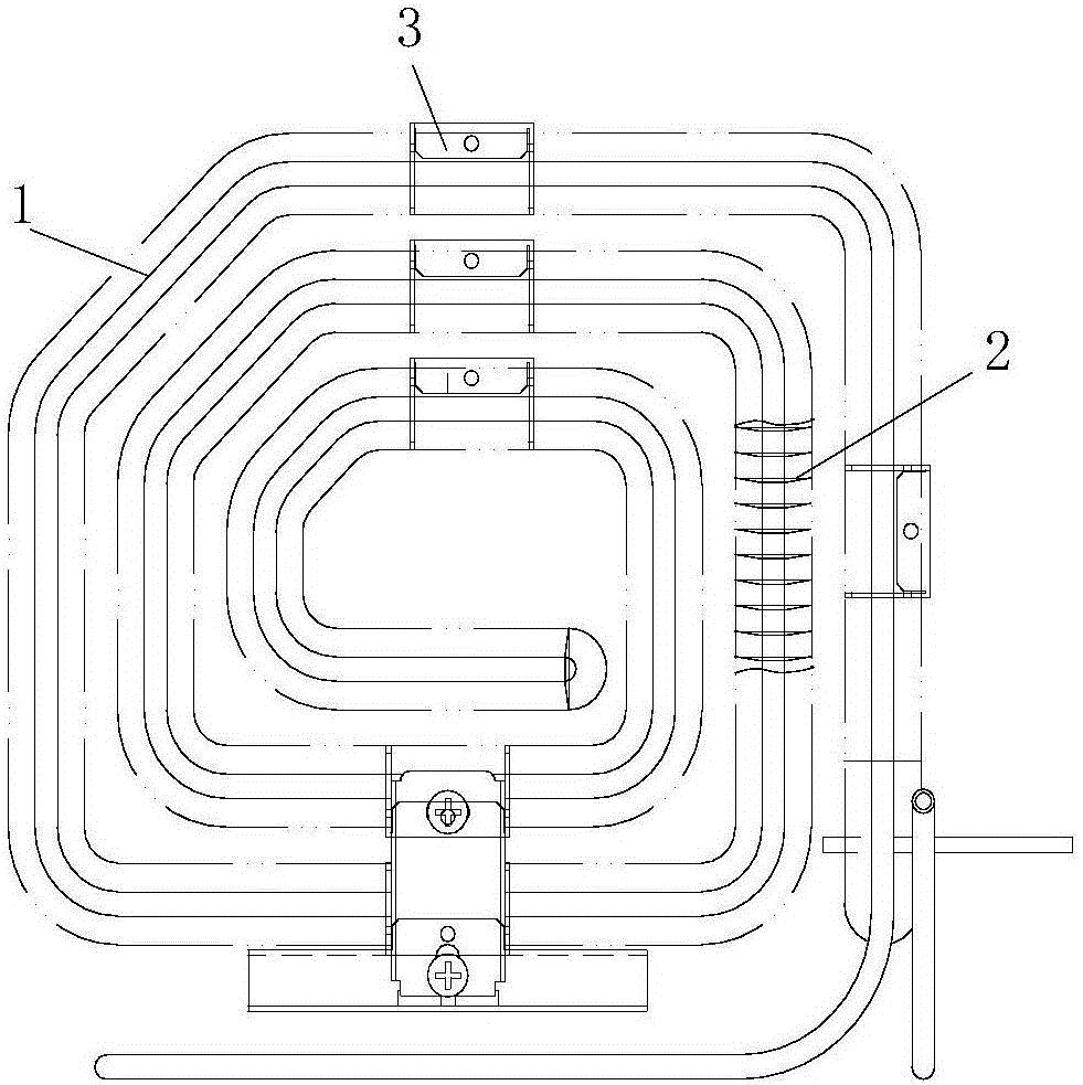
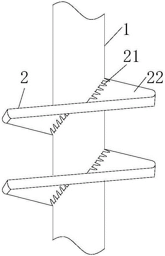
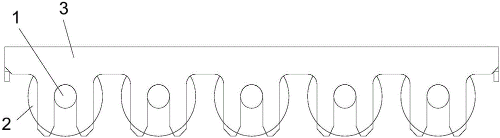
[0031] Example 1, such as Figure 1 to Figure 6 , The spiral fin condenser includes a condenser tube 1 and a fin 2. The fin 2 is spirally wound on the surface of the condenser tube 1. The inner side of the fin 2 connected with the heat dissipation tube 1 is a wave structure 21, The outer side is a smooth structure 22, and the inner side is connected by a wave-like structure. On the one hand, it is firmly connected and not easy to slide. It can disperse the force from the outside during the assembly process and is not easy to be damaged. On the other hand, it is used to guide and correct heat. The hot air flow is guided to quickly dissipate heat; the smooth structure on the outside can ensure that the heat dissipation direction formed by the fins during heat dissipation is uniform and overall linear heat dissipation. If the wave structure continues, it will cause the heat sink to dissipate non-linearly. The heat radiation has crossover and overlap, and the heat radiation waves wi...

Embodiment 2

[0035] Example 2, such as Figure 7 Of course, the card is a rigid structure. In order to prevent it from breaking and to shrink the card smoothly, three adjustment slots 325 are provided at the bottom of the card slot 324, which extend to the mounting plate.

Embodiment 3

[0036] Example 3, such as Figure 8-11 The fixed bracket 3 includes a mounting plate 31 and a plurality of cards 323 on both sides respectively. The cards on both sides are staggered. The two sides of the mounting plate are bent twice to form a T-shaped structure. Generally speaking, the first The second bend is 180° at A, and the second bend is 90° at B. Of course, the bending sequence can also be reversed. A slot 324 is formed between the cards 323 on both sides that is compatible with the condenser tube. The end of the mounting plate becomes the limit part to ensure that the condenser tube is stuck in the card slot. The plane of the card is lower than the plane of the mounting plate, so that all the cards can be on the same plane after bending and forming, which can effectively correct The condenser tube is clamped and fixed, and the mounting plate can cover more fins to prevent deformation of the fins when the fixed bracket or condenser is installed.

[0037] Such as Pictur...


PUM


Abstract

The invention relates to a spiral fin condenser. The spiral fin condenser comprises a condensation pipe and a fin; the fin is spirally wound on the surface of the condensation pipe; and the condensation pipe is twisted and bent by multiple times to form a cuboid structure. The spiral fin condenser further comprises a fixed bracket fixedly clamped on the condensation pipe. The spiral fin condenser has such characteristics as small size, compact structure and good condensation effect.

Description

Technical field [0001] The invention relates to the technical field of condensers, in particular to a spiral fin type condenser. Background technique [0002] Existing condensers generally use water condensers, longitudinal mixing tube bundle condensers, wire-tube condensers, etc. In order to achieve a better cooling effect, existing condensers generally have the characteristics of large heat dissipation area, which produces One drawback is the large size, which results in high costs, and greatly restricts the application; and once a small-sized condenser is used, there will be a defect of poor heat dissipation performance. [0003] The Chinese invention patent with the patent number 200610111866.5 provides a spiral fin condenser, which includes a spiral fin tube 15, a horizontal fixing member 20 and a vertical fixing member 30. The spiral fin tube 15 is bent into a serpentine shape for the first time so as to be horizontally arranged and fixed by the horizontal fixing member 20, ...

Claims


Application Information

Patent Timeline
Patent Type & Authority Applications(China)
IPC IPC(8): F25B39/04F28F1/36F28F9/013
CPCF25B39/04F25B2339/04F25B2500/06F25B2500/13F25B2500/17F28F1/36F28F9/0131F28F2265/30
Inventor 郑磊陈建元
Owner CHANGZHOU CHANGZHENG HEAT EXCHANGER TECH
Why Eureka
Try Eureka