Broadband circular polarized antenna

A circularly polarized antenna and broadband technology, applied in antennas, resonant antennas, electrical short antennas, etc., can solve the problems of limited communication distance, narrow axial ratio bandwidth, low antenna gain, etc., to overcome narrow bandwidth, wide axis Specific bandwidth, overcoming the effect of low gain

Active Publication Date: 2016-12-07
XIDIAN UNIV
View PDF6 Cites 2 Cited by
  • Summary
  • Abstract
  • Description
  • Claims
  • Application Information

AI Technical Summary

Problems solved by technology

The shortcomings of this antenna are that the antenna gain is low, the axial ratio bandwidth is narrow, and it is difficult to meet the actual needs
The disadvantage of this antenna is that the bandwidth of the antenna is extremely narrow, and it is difficult to meet the current multi-field requirements
[0005] To sum u

Method used


Image

  • Broadband circular polarized antenna
  • Broadband circular polarized antenna
  • Broadband circular polarized antenna

Examples


Example Embodiment

[0030] Example 1:

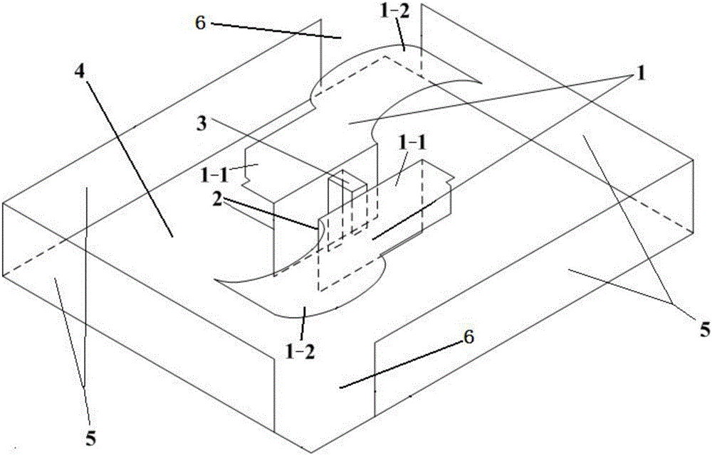
[0031] Reference figure 1 and figure 2 , The present invention provides a broadband circularly polarized antenna, comprising a rectangular metal floor 4 parallel to the horizontal plane, a group of adjacent sides of the metal floor 4 and another group opposite to the group of adjacent sides There are L-shaped metal fences 5 on the adjacent sides of the group; the adjacent ends of the two metal fences 5 are not connected, so that two gaps 6 are formed between the two metal fences 5, and the two gaps 6 It is 180° rotationally symmetrical in the horizontal plane; the middle of the metal floor 4 is fixed with two opposite vertical metal sheets 2 along the vertical direction, and the two vertical metal sheets 2 are 180° rotationally symmetrical in the horizontal plane; each The upper end of the vertical metal sheet 2 is connected to a horizontal metal sheet 1. The horizontal metal sheet 1 includes a horizontal sheet body 1-1 parallel to the metal floor 4 and a hor...

Example Embodiment

[0032] Example 2:

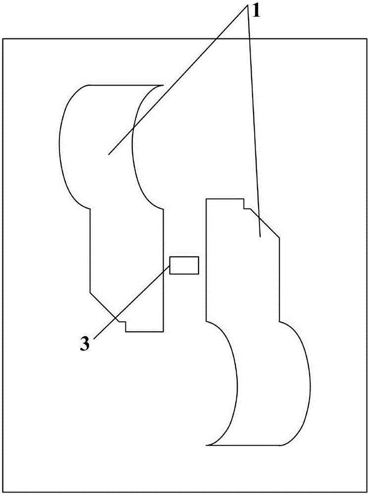
[0033] On the basis of Example 1, the ratio of the major axis of the ellipse to the minor axis of the ellipse of the semi-elliptic curve side is ≥2. The semi-elliptical arc surface 1-2 extends from the side of the horizontal sheet body 1-1 perpendicular to the vertical metal sheet 2. The horizontal sheet body 1-1 is provided with a cut corner relative to one end of the semi-elliptical arc surface 1-2, and the cut corner shape can be triangle, rectangle or sector; different shapes and sizes of the cut corners affect the antenna The axial ratio (that is, the ratio of the amplitude of the electric field components in the two orthogonal directions of the electromagnetic wave radiated by the antenna at a certain point in space) has a certain effect. After continuous simulation and optimization, the final choice is figure 1 with figure 2 The triangular-like shape cut corner shown can obtain the best axial ratio bandwidth performance. The semi-elliptic curve side o...


PUM


Abstract

The invention provides a broadband circular polarized antenna comprising a metal floor which is parallel to a horizontal plane, one group of adjacent edges of the metal floor and the other group of adjacent edges opposite to the one group of adjacent edges are provided with L-shaped metal fences, two gaps are formed between the two metal fences, the two gaps are in a 180 degree rational symmetry relation on the horizontal plane, two opposite vertical metal sheets are fixed at a middle part of the metal floor, the two vertical metal sheets are in a 180 degree rational symmetry relation on the horizontal plane, an upper end of each metal sheet is connected with a horizontal metal sheet, the horizontal metal sheet comprises a horizontal sheet body which is parallel to the metal floor and a semi-ellipse cambered surface which extends outward from one end of the horizontal sheet body, the two horizontal metal sheets are in a 180 degree rational symmetry relation on the horizontal plane, and an r-shaped feed line is arranged between the two vertical metal sheets. The broadband circular polarized antenna is simple in structure, large in impedance bandwidth and axial ratio bandwidth and high in gain and is capable of generating circular polarized waves, and the broadband circular polarized antenna also has a stable far field radiation directional diagram.

Description

technical field [0001] The invention belongs to the technical field of microwave antennas, in particular to a broadband circularly polarized antenna in the field of wireless communication. Background technique [0002] With the rapid development of wireless technology, antenna technology with various functions has been widely developed. Most of the current antennas are linearly polarized antennas, which are usually simple in structure and easy to implement, but they are often limited by antenna orientation and multipath effects in practical applications. Circularly polarized antennas have received great attention because they can receive incoming waves with arbitrary polarization and reduce multipath effects. [0003] Shenzhen University proposed a circularly polarized antenna based on crossed dipoles in its patent application "A circularly polarized crossed dipole antenna and its preparation method" (application number: 201310420597.0, publication number: 103474765A). The...

Claims


Application Information

Patent Timeline
IPC IPC(8): H01Q9/04
CPCH01Q9/0428
Inventor 史琰康楷
Owner XIDIAN UNIV
Why Eureka
Try Eureka