High-speed laser projection line peak value detection method

A technology of laser projection and peak detection, which is used in image data processing, instruments, computing, etc., and can solve problems such as the inability to meet high-precision detection requirements and the sensitivity of image sensors to noise.

Inactive Publication Date: 2016-12-14
苏州光图智能科技有限公司
View PDF4 Cites 1 Cited by
  • Summary
  • Abstract
  • Description
  • Claims
  • Application Information

AI Technical Summary

Problems solved by technology

[0003] The interpolation technology commonly used above is more sensitive to the noise of the image sensor, and cannot meet some high-precision detection requirements in the case of serious interference.

Method used


Image

  • High-speed laser projection line peak value detection method
  • High-speed laser projection line peak value detection method
  • High-speed laser projection line peak value detection method

Examples


Embodiment Construction

[0009] The preferred embodiments of the present invention will be described in detail below in conjunction with the accompanying drawings, so that the advantages and features of the present invention can be more easily understood by those skilled in the art, so as to define the protection scope of the present invention more clearly.

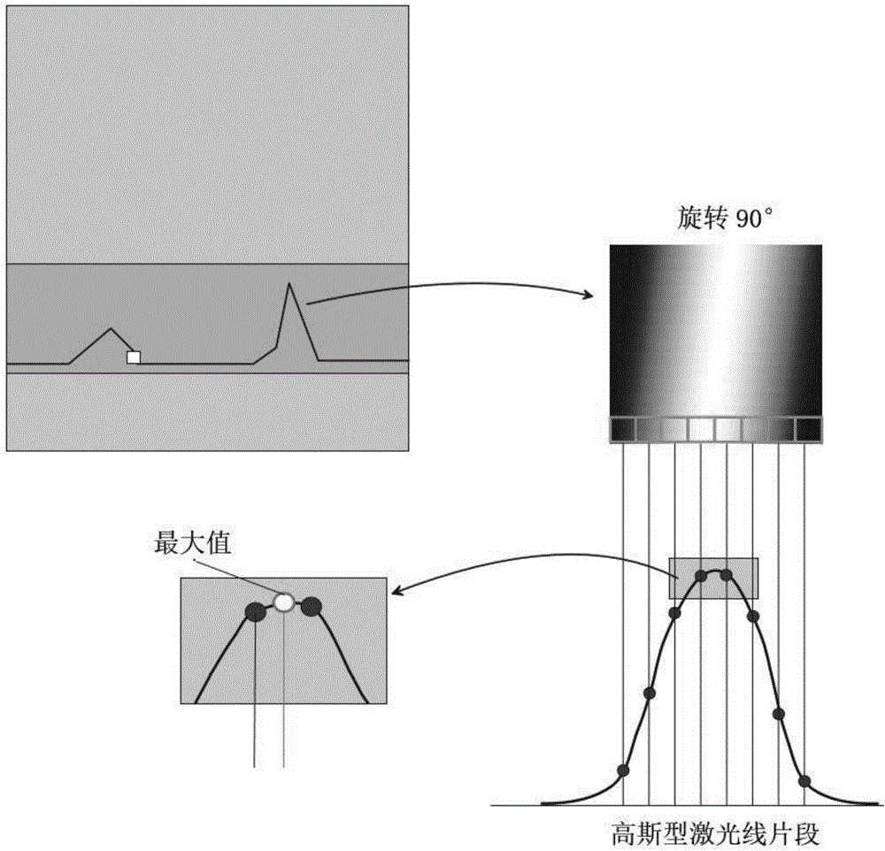
[0010] See attached figure 2 As shown, in the measurement method of high-speed laser peak detection in this embodiment, two adjacent peak pixels in the image projected by the Gaussian laser are subdivided into 64 data sampling points according to the gray area effect ratio of adjacent pixels , by applying the Gaussian peak detection algorithm to the above 64 data points, analyze and judge whether there is a laser center (that is, the maximum value) and a laser boundary within the sub-pixel accuracy of the two pixels, that is, determine the highest probability of matching with the Gaussian model The sampling point is used as the peak point, so as...


PUM


Abstract

The invention discloses a high-speed laser projection line peak value detection method. Two adjacent peak value pixels in an image projected by Gaussian laser is divided into 64 data sampling points according to a grayscale area effect ratio of the adjacent pixels, and the sampling point with the highest probability matched with a Gaussian model is analyzed and determined as the peak point from the 64 data points by employing a Gaussian peak value detection algorithm so that a laser center and a laser boundary can be detected in terms of the sub-pixel precision. According to the method, the measuring precision is ultrahigh.

Description

technical field [0001] The invention relates to the application field of non-contact measurement, in particular to a measurement method based on laser projection peak detection. Background technique [0002] At present, in the measurement method based on laser triangulation, nonlinear interpolation technology is commonly used to determine the center position and boundary position of the laser line in the projected image, so as to achieve a recognition accuracy beyond the resolution capability of the image sensor. The currently commonly used interpolation technology For the weighted center of gravity method. The principle of the weighted center of gravity method is to take the pixels within the brightness threshold range on the laser boundary, take their positions and add them according to a certain weight, and take the average as the final boundary position. After obtaining the boundaries on both sides, take the middle of the two boundaries The dot position is taken as the ...

Claims


Application Information

Patent Timeline
Patent Type & Authority Applications(China)
IPC IPC(8): G06T7/00G06T7/60
CPCG06T2207/10004
Inventor 何鹏
Owner 苏州光图智能科技有限公司
Why Eureka
Try Eureka