Multi-Axis Chip-Scale MEMS Inertial Measurement Unit (IMU) Based on Frequency Modulation

a frequency modulation and inertial measurement technology, applied in the direction of speed/acceleration/shock measurement devices, instruments, surveying and navigation, etc., can solve the problems of not meeting the navigation grade requirements of current mems imus, few systems reaching the tactical grade, and not allowing further miniaturization and cost reduction. , to achieve the effect of wide measurement bandwidth, wide dynamic range, and ultra-high precision

Active Publication Date: 2014-07-31
RGT UNIV OF CALIFORNIA
View PDF3 Cites 69 Cited by
  • Summary
  • Abstract
  • Description
  • Claims
  • Application Information

AI Technical Summary

Benefits of technology

[0014]The disclosed temperature and vibration immune, inherently quasi-digital, multi-axis MEMS inertial measurement unit (IMU), has ultra-high precision, stability, and wide dynamic range and wide measurement bandwidth. The IMU is based upon frequency modulated (FM) accelerometers and gyroscopes. Due to the inherent FM nature of the IMU, it provides a resolution and stability unprecedented in conventional inertial MEMS devices. The disclosed IMU provides a unique differential frequency measurement technique and enables simultaneous detection (and decoupling) of the true inertial inputs (angular rate and acceleration) as well as the temperature distribution across the chip-scale system. In this approach, the IMU becomes its own thermometer, eliminating the commonplace need for thermal calibration and issues with thermal lags and hysteresis. Also, the disclosed architecture is robust against mechanical and electromagnetic interferences due to the inherent advantages of frequency modulated signals (quasi-digital) compared to amplitude modulated signals (analog). An availability of high stable references of frequency enables to achieve stability of 10−9 in the FM system, providing a 1000 times improvement over the state-of-the-art conventional AM gyroscopes with capacitive pick-off.

Problems solved by technology

Current MEMS IMUs do not meet the navigation grade requirements, and very few systems are reaching the tactical grade due to limitations in temperature and vibration sensitivity, signal stability, resolution, dynamic range, and bandwidth.
This approach does not allow further miniaturization and cost reduction since individual dies have to be fabricated, packaged, and tested separately.
Also, conventional sensors based on analog amplitude modulation do not provide the necessary stability and immunity to vibration and temperature.
However, for both methods alignment errors will vary for each device due to temperature, ambient vibrations, shock, accelerations, life span of IMU, limiting the effectiveness of factory calibration.
This method also suffers from the inherent limitations of the conventional MEMS sensors operating based on analog amplitude modulation of signals.
Despite these advantages, there are significant drawbacks to this IMU architecture.
First, creating conventional gyroscope(s) and accelerometer(s) requires very different packaging parameters.
This fundamental difference between packaging of high performance MEMS gyroscopes and accelerometers makes true co-fabrication and co-packaging impossible, preventing true integration.
Variation of these internal parameters with time and with varying environment produces unpredictable drifts in the sensor output.
Another inherent disadvantage of conventional MEMS sensors using amplitude modulated signals comes from the limited dynamic range (the ratio between the full scale linear range and the smallest useful signal).
In the best case scenario, AM capacitive readout with preselected low-noise electronic components can only achieve a resolution of 1×10⁻⁶ of the full scale, with a practical limit of 1×10⁻⁵.
This means that achieving a 106 dynamic range and 1 ppm stability (requirement of the navigation grade) is practically impossible with conventional MEMS sensors.
These fundamental limitations on the dynamic range and output stability prevent the use of MEMS gyroscopes and accelerometers in many important applications.
AM architecture of sensors also presents tradeoffs between sensor noise and bandwidth (classic gain vs. bandwidth tradeoff of analog AM systems).
The conventional AM based inertial sensor operation is also sensitive to temperature, resulting in significant response drifts over ambient temperature and pressure variations.
The stability of the analogue signal reference is limited by 10−6, that fact creates irresolvable limitations on the AM devices stability.
These constraints stem from a fundamental Q versus bandwidth tradeoff and dynamic range limitations of analog amplitude modulation (AM) systems (in conventional MEMS gyroscopes, the sense-mode response is excited by the input angular rate amplitude-modulated by the drive-mode velocity).
The conventional AM based gyroscopes operation is also sensitive to the value of the sense-mode Q-factor, resulting in significant response drifts over ambient temperature and pressure variations.
The fact that conventional MEMS gyroscopes are inherently resonant devices while conventional MEMS accelerometers are inherently non-resonant devices makes it impossible to truly integrate them together.
The main challenge to overcome in this approach is temperature sensitivity of the resonant frequency, caused by the dependency of the silicon's Young's modulus on temperature.

Method used


Image

  • Multi-Axis Chip-Scale MEMS Inertial Measurement Unit (IMU) Based on Frequency Modulation
  • Multi-Axis Chip-Scale MEMS Inertial Measurement Unit (IMU) Based on Frequency Modulation
  • Multi-Axis Chip-Scale MEMS Inertial Measurement Unit (IMU) Based on Frequency Modulation

Examples


Embodiment Construction

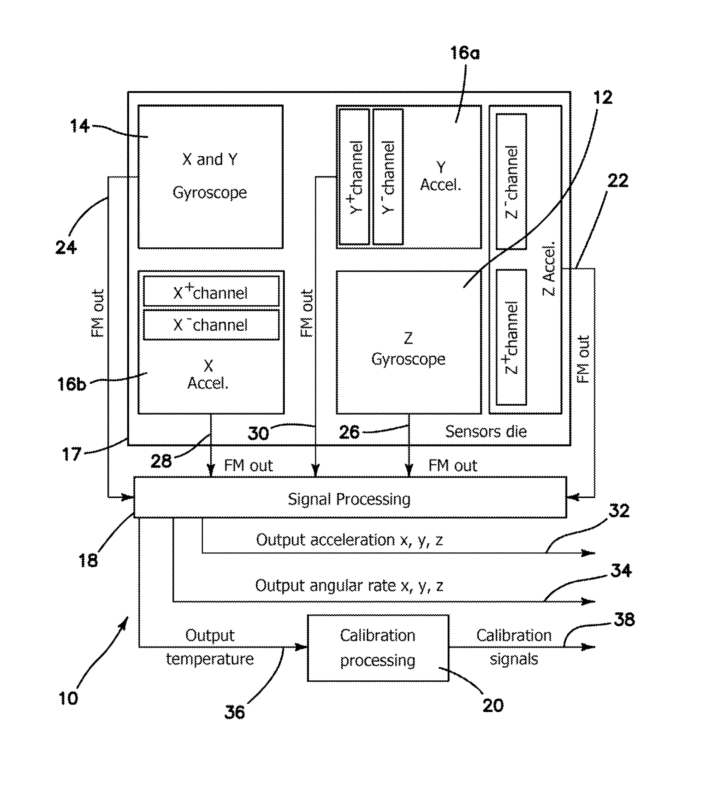
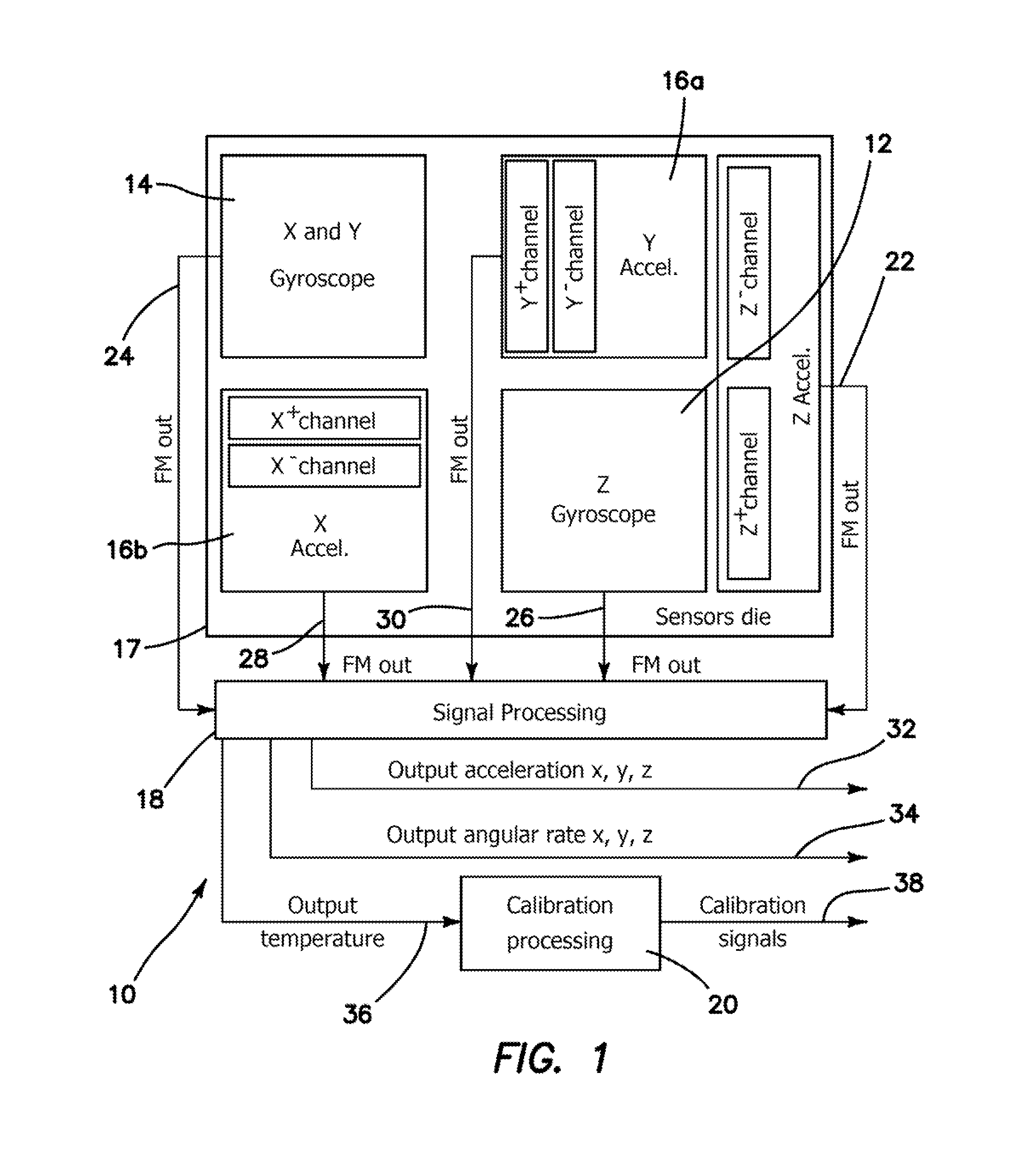
[0046]What is disclosed is the first multi-axis MEMS IMU 10 with an inherently FM-based, quasi-digital architecture and including a method of operation and self-calibration of the same. FIG. 1 is a block diagram of a 3-axis IMU implementation which was realized as single-chip solution as a proof of concept, combining an ultra-high Q-factor z-axis FM gyroscope co-fabricated with two complementary high-resolution FM accelerometers (x and y axis). The illustrated embodiment shows a differential FM accelerometer using two acceleration sensitive tuning fork resonators equipped with negative electrostatic springs. IMU 10 is fabricated on a single die 17 and includes a z-axis MEMS gyroscope 12 to provide a Z+ and Z− channel FM acceleration output 22. Z-axis MEMS gyroscope 12 also provides an angular rate FM output 26. An x and y axis MEMS gyroscope 14 provides an FM angular rate output 24. Die 17 also includes a y MEMS accelerometer 16a with Y+ and Y− channel acceleration outputs provided ...


PUM


Abstract

A multi-axis microelectromechanical-systems (MEMS) inertial measurement unit (IMU) is fabricated in a vacuum sealed single packaged device. An FM vibratory gyroscope and an FM resonant accelerometer both for generating FM output signals is fabricated in the silicon chip using MEMS. A signal processor is coupled to the an FM vibratory gyroscope and to the FM resonant accelerometer for receiving the FM gyroscopic output signals and the FM accelerometer output signals. The signal processor generates simultaneous and decoupled measurement of input acceleration, in put rotation rate, and temperature and / or temperature distribution within the IMU, self-calibration of the biases and scale factors of the IMU and its support electronics against temperature variations and other common mode errors, and reduction of the cross axis sensitivity by reducing acceleration errors in the gyroscope and rotation errors in the accelerometer.

Description

GOVERNMENT RIGHTS[0001]This invention was made with government support under Grant No. N00014-11-1-0483 awarded by the Office of Naval Research. The government has certain rights in the invention.BACKGROUND[0002]1. Field of the Technology[0003]The disclosure relates to the field of multi-axis MEMS inertial measurement units (IMU) and in particular to units that exhibit temperature and vibration immunity, which are inherently quasi-digital, have ultra-high precision, stability, and wide dynamic range and wide measurement bandwidth.[0004]2. Description of the Prior Art[0005]All inertial measurement units (IMUs) are based on a combination of inertial sensors such as gyroscopes and accelerometers. The performance parameters of an IMU are defined by the parameters of the individual inertial sensors, as well as the method of processing the individual measurements together. Current MEMS IMUs do not meet the navigation grade requirements, and very few systems are reaching the tactical grade...

Claims


Application Information

Patent Timeline
Patent Type & Authority Applications(United States)
IPC IPC(8): G01P21/00
CPCG01P21/00G01C19/5783G01P15/097G01P15/125G01P15/18
Inventor TRUSOV, ALEXANDER A.ZOTOV, SERGEI A.SHKEL, ANDREI M.
Owner RGT UNIV OF CALIFORNIA
Why Eureka
Try Eureka