Vehicle-mounted display device

A vehicle-mounted display and display technology, applied in optical observation devices, vehicle parts, transportation and packaging, etc., can solve the problem of inability to assist the driver

Inactive Publication Date: 2016-12-14
MITSUBISHI ELECTRIC CORP
View PDF8 Cites 9 Cited by
  • Summary
  • Abstract
  • Description
  • Claims
  • Application Information

AI Technical Summary

Problems solved by technology

In addition, the above-mentioned Patent Documents 1 and 2 have the problem that the passenger cannot freely select which part of the vehicle's periphery the camera image is displayed on the screen, and the driver cannot be guided based on the selected camera image. auxiliary

Method used


Image

  • Vehicle-mounted display device
  • Vehicle-mounted display device
  • Vehicle-mounted display device

Examples


Embodiment approach 1

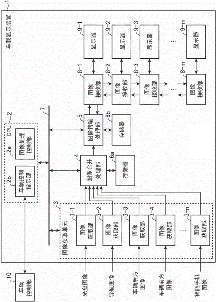
[0032] like figure 1 As shown, the vehicle-mounted display device 1 according to Embodiment 1 includes: a CPU (Central Processing Unit: central processing unit) 2 that controls the overall operation, and an image acquisition unit 3 composed of a plurality of image acquisition units 3-1 to 3-n. , an image integration processing section 4 for synthesizing and merging a plurality of images, an image transmission processing section 5 for transmitting image data to the image receiving sections 8-1 to 8-m, and an image receiving the image data transmitted by the image transmission processing section 5 Receivers 8-1 to 8-m, and displays 9-1 to 9-m that display received image data. In addition, the vehicle control unit 10 that controls the on-vehicle equipment mounted on the vehicle and the on-vehicle display device 1 are connected via an in-vehicle network.

[0033] The CPU 2 includes an image processing control unit 2 a that controls the overall image processing of the on-vehicle d...


PUM


Abstract

A vehicle-mounted display device (1) is provided with: a plurality of displays (9-1 to 9-m) installed in a vehicle; a plurality of operation receiving units (for example, touch panels) corresponding to the plurality of displays (9-1 to 9-m); an image acquisition unit (3) which selects a plurality of camera images from a plurality of vehicle exterior cameras that capture images of the surroundings of the vehicle; an image processing control unit (2a) which provides an image processing instruction for generating image data to be displayed on a display corresponding to an operation receiving unit that has received, from an occupant, an operation for selecting a camera image for display on the display (9-1 to 9-m) from among the plurality of camera images; and an image integration processing unit (4) which selects camera images to be displayed on each of the plurality of displays (9-1 to 9-m) from among the plurality of camera images according to image processing instructions of the image processing control unit (2a) and generates image data.

Description

technical field [0001] The present invention relates to an in-vehicle display device for displaying a camera image obtained by photographing the periphery of a vehicle on a display installed in the vehicle. Background technique [0002] By displaying the camera images captured around the vehicle on the monitor installed in the vehicle, the occupants can observe obstacles and approaching objects (other vehicles, motorcycles, bicycles, pedestrians, etc.) in the front, rear, left, and right of the vehicle on the monitor. . The occupants of the front passenger seat or the rear seat confirm the surrounding conditions of the vehicle on the display and communicate it to the driver, or use it for safety confirmation when they get off the vehicle, thereby forming driving assistance for the driver. [0003] For example, in the vehicle-mounted electronic device disclosed in Patent Document 1, when a rear seat occupancy is detected by a rear seat occupancy detection sensor, a rear seat...

Claims


Application Information

Patent Timeline
Patent Type & Authority Applications(China)
IPC IPC(8): B60R1/00H04N7/18
CPCH04N7/181B60R2300/207B60R1/00B60R2300/105B60R2300/303B60R2300/8093G06V20/58H04N23/63G06T3/40G06T11/60
Inventor 加藤圣崇星原靖宪
Owner MITSUBISHI ELECTRIC CORP
Why Eureka
Try Eureka