Navigation Device with Camera-Info
a technology of navigation device and camera information, applied in navigation instruments, traffic control systems, instruments, etc., can solve the problems of difficult to translate this quite abstract version of the real world into something, stylised or schematic representations that are still relatively difficult to be understood by users, etc., to simplify pattern recognition techniques, increase accuracy, and facilitate recognition
- Summary
- Abstract
- Description
- Claims
- Application Information
AI Technical Summary
Benefits of technology
Problems solved by technology
Method used
Image
Examples
embodiment 1
[0080]FIG. 5 depicts a first example of the invention. FIG. 5 shows a still of the image registered by the camera 24 as displayed by the navigation device 10. As can be seen, an arrow 5 indicating a right turn is superimposed by the processor unit 11. According to this embodiment, a user-friendly image is displayed to the user, allowing easy interpretation. This embodiment has the advantage that no complex mathematics and data processing is needed.
[0081]Instead of the navigation direction depicted in FIG. 5, also other navigation directions as mentioned above may be displayed, including perspective shaped navigation directions, such as perspective shaped arrows.
embodiment 2
[0082]FIG. 6 shows another still of the image registered by the camera 24. According to this example, the navigation device 10 superimposes the route 4 and the arrow 5. The route 4 and the arrow 5 are superimposed in such a way that their position on the display 18 corresponds with the image as provided by the camera 24. FIG. 6 clearly shows that the route 4 is displayed such that it corresponds with the road as shown on the display 18. Also, the arrow 5 is displayed in such a way that it accurately indicates a right turn in the image as provided by the camera 24.
[0083]It will be understood that the embodiment shown in FIG. 5 can easily be obtained by superimposing or combining the image as provided by the camera 24 and a navigation direction, as for instance the arrow 5. However, in order to create the image as provided in FIG. 6, more complicated data processing is required in order to match the image as provided by the camera 24 with the navigation directions. This will be explai...
third embodiment
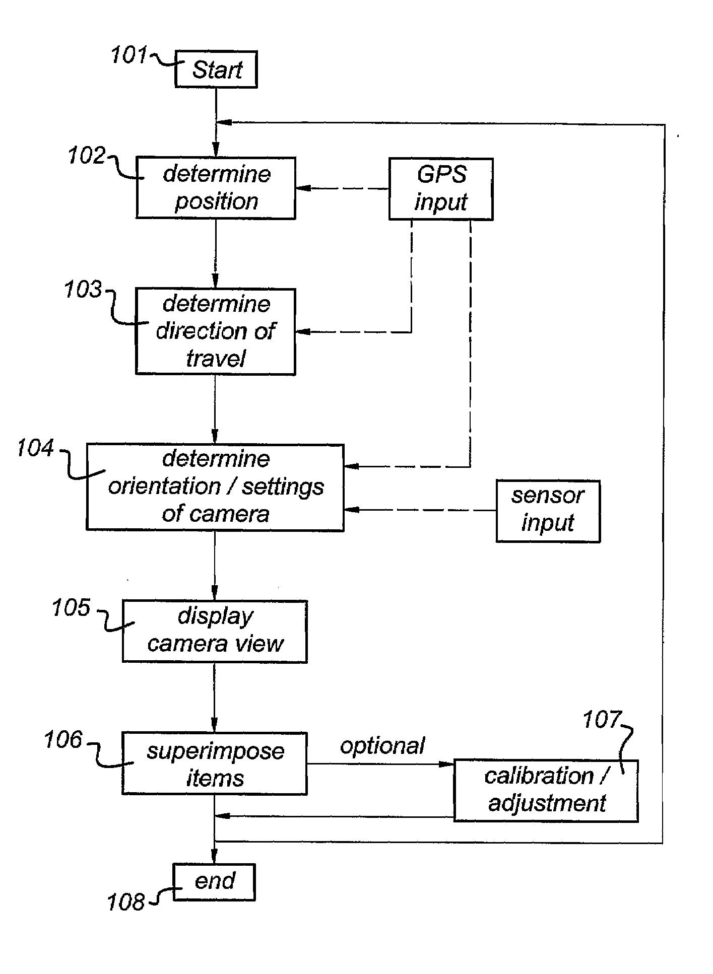
[0116]According to a third embodiment, the navigation directions are superimposed over the camera image by using pattern recognition techniques.
[0117]In recent years, considerable progress has been made in the field of real time analysis of image frames (e.g. a video feed such as provided by camera 24) to identify actual objects in the video feed. The literature is quite extensive in this area: reference may for example be made to U.S. Pat. No. 5,627,915 (Princeton Video Image Inc.) in which video from a scene such as a sports stadium is analysed by pattern recognition software; an operator manually indicates high contrast areas in the stadium (e.g. lines marked on the playing surface; edges of the playing surface; billboards) and the software builds up a geometrical model of the entire stadium using these high contrast landmarks. Then, the software is able to analyse a real time video feed looking for these landmarks; it is then able to take a stored computer generated image (e.g. ...
PUM
 Abstract
Description
Claims
Application Information
 - R&D
- Intellectual Property
- Life Sciences
- Materials
- Tech Scout
- Unparalleled Data Quality
- Higher Quality Content
- 60% Fewer Hallucinations
Browse by: Latest US Patents, China's latest patents, Technical Efficacy Thesaurus, Application Domain, Technology Topic, Popular Technical Reports.
© 2025 PatSnap. All rights reserved.Legal|Privacy policy|Modern Slavery Act Transparency Statement|Sitemap|About US| Contact US: help@patsnap.com


