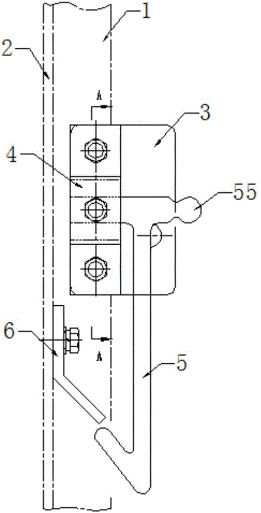
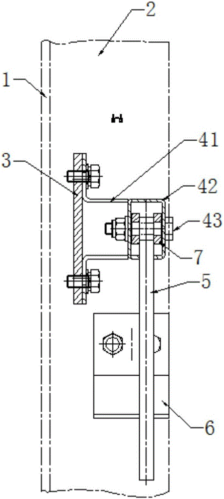
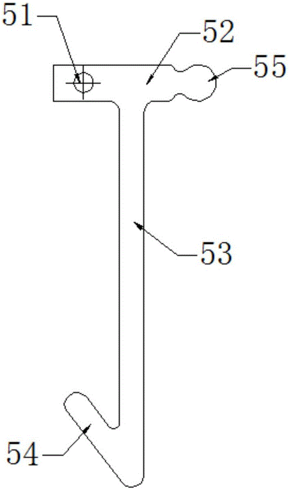
Suspension cage flap gate lock

A flap door and door lock technology, which is applied in the field of door locks for hanging cage flap doors, can solve the problems of easy opening of flap doors, hidden dangers, falling transported goods, etc., and achieves the effect of simple and convenient operation.

Inactive Publication Date: 2016-12-21
TIANJIN JINGLONG ENG MACHINERY
View PDF0 Cites 4 Cited by
  • Summary
  • Abstract
  • Description
  • Claims
  • Application Information

AI Technical Summary

Problems solved by technology

[0002] The lower door of the double door of the hanging cage is a flap door. The flap door is easy to open during the transportation of the cage, causing the transported goods to fall, which makes the hanging cage with the flap door a certain safety hazard during construction on the construction site.

Method used


Image

  • Suspension cage flap gate lock
  • Suspension cage flap gate lock
  • Suspension cage flap gate lock

Examples


Embodiment Construction

[0027] It should be noted that, in the case of no conflict, the embodiments of the present invention and the features in the embodiments can be combined with each other.

[0028] In describing the present invention, it should be understood that the terms "center", "longitudinal", "transverse", "upper", "lower", "front", "rear", "left", "right", " The orientations or positional relationships indicated by "vertical", "horizontal", "top", "bottom", "inner" and "outer" are based on the orientations or positional relationships shown in the drawings, and are only for the convenience of describing the present invention and Simplified descriptions, rather than indicating or implying that the device or element referred to must have a particular orientation, be constructed and operate in a particular orientation, and thus should not be construed as limiting the invention. In addition, the terms "first", "second", etc. are used for descriptive purposes only, and should not be understood ...


PUM


Abstract

The invention provides a suspension cage flap gate lock. The suspension cage flap gate lock comprises a lower wheel gate baffle plate, a lock bracket, a lock hook and a lock plate. The lock hook is T-shaped, and one side at the upper end of the lock hook is provided with a rotary hole perpendicular to the plane where the lock hook is located, and the rotary hole and a hook angle at the bottom of the lock hook are a same direction of the lock hook. The lock bracket consists of bending plates, a fixed frame and a fixed part. The pair of bending plates are relatively fixed on the lower wheel gate baffle plate. One end of the fixed frame is fixed at the outer ends of the bending plates, and the fixed frame is relatively equipped with a group of fixation holes. One side at the upper end of the lock hook is inserted into the fixed frame, the rotary hole is located between the group of fixation holes, and the fixed part passes through the fixation holes and the rotary hole and is fixed on the fixed frame. The lock plate is obtuse angle folded-plate shaped, the upper end of the lock plate is vertically fixed, and the lower end is opposite to the lower end hook angle of the lock hook. The suspension cage flap gate lock provided by the invention utilizes a gravitational self-lock structure to realize self-lock of the flap gate, and prevents accidental opening of the flap gate during operation to cause accidents.

Description

technical field [0001] The invention belongs to the technical field of hanging cages, in particular to a door lock for a flap door of a hanging cage. Background technique [0002] The lower door of the double door of the hanging cage is a flap door, and the flap door is easy to open during the transportation of the cage, resulting in the falling of the transported goods, which makes the hanging cage with the flap door a certain safety hazard during construction on the construction site. Contents of the invention [0003] In view of this, the present invention aims to propose a door lock for the flap door of the hanging cage. Through the self-locking structure of the flap door lock using gravity, the self-locking of the flap door is realized, and the accidental locking of the flap door during operation is prevented. open and cause an accident. [0004] In order to achieve the above object, technical solution of the present invention is achieved in that way: [0005] A doo...

Claims


Application Information

Patent Timeline
Patent Type & Authority Applications(China)
IPC IPC(8): E05C19/12
CPCE05C19/12
Inventor 马文凯郭立成
Owner TIANJIN JINGLONG ENG MACHINERY
Why Eureka
Try Eureka