
Transmission with electric motor and switchable gear unit

A technology of transmission device and auxiliary reducer, which can be used in transportation and packaging, brakes, mechanical equipment, etc., can solve problems such as increased fuel consumption, and achieve the effect of improving driving power.

Inactive Publication Date: 2020-03-06
ZF FRIEDRICHSHAFEN AG
View PDF1 Cites 0 Cited by
  • Summary
  • Abstract
  • Description
  • Claims
  • Application Information

AI Technical Summary

Problems solved by technology

[0007] However, the hydrodynamic retarder also generates an undesired traction torque in the cut-off state, which is caused by the gas exchange loss inside the working chamber of the retarder and by the bearing friction of the rotor shaft bearing, and the traction force The torque has to be compensated by the torque of the internal combustion engine and thus has the effect of increasing fuel consumption

Method used


Image

  • Transmission with electric motor and switchable gear unit

Examples


Embodiment Construction

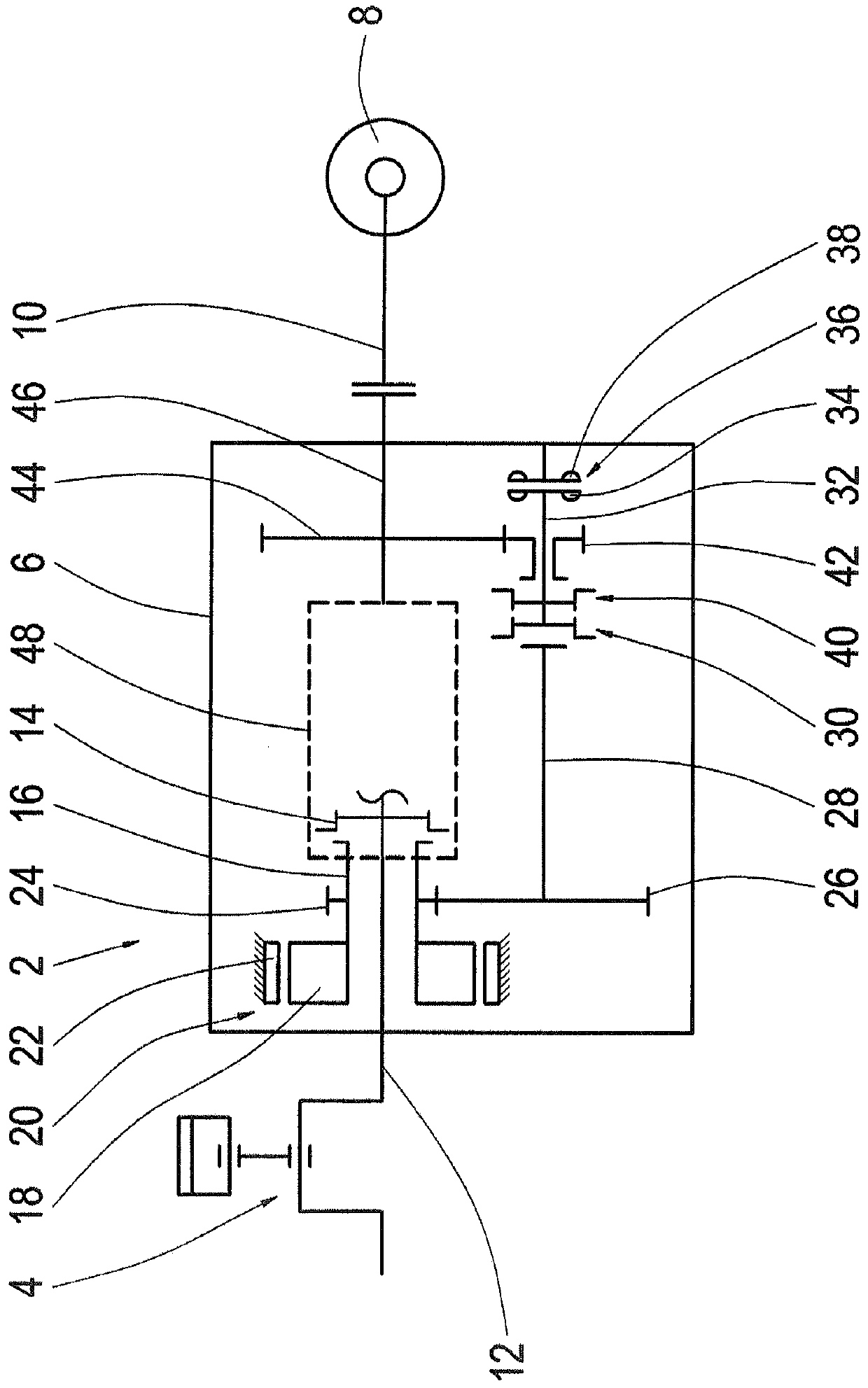
[0026] only figure 1 The drive train 2 of a vehicle, which is not shown in detail, is shown in a schematic illustration and includes a drive motor 4 , which is generally designed as an internal combustion engine, as well as a transmission 6 and a cardan shaft 10 connected to wheels 8 . A friction clutch, not shown here, can be provided between the drive engine and the transmission 6, in transmissions that do not otherwise implement the starting function of the vehicle and support during shifting processes within the transmission , the friction clutch is used to perform these functions. Into the transmission 6 an input shaft 12 is introduced, on which at least one component of the shift element 14 is arranged in a rotationally fixed manner. Arranged around the input shaft 12 in the form of a hollow shaft is a rotor shaft 16 which surrounds the input shaft 12 at the input of the transmission 6 . A rotor 18 of an electric machine 20 is arranged on the rotor shaft 16 . The roto...


PUM


Abstract

In a transmission (6) having a motor (20) and a hydraulic reducer (36) comprising a rotor (34), the rotor (34) can be connected to a driven shaft(46) of the transmission (6) via a first switching element (40). The rotor (34) of the hydraulic reducer (36) can also be connected to the rotor (18) of the motor (20) via a second switching element (30). A third switching element (14) is arranged for connecting the rotor (18) of the motor (20) to the input shaft (12) of the transmission (6). The first switching element (40) and the second switching element (30) are engaged in order to form an auxiliary speed reducer composed of the hydraulic reducer (36) and the motor (20) and acting on the driven shaft (46). The second switching element (30) and the third switching element (14) are engaged in order to form a main speed reducer composed of a hydraulic reducer (36) and a motor (20) and acting on the input shaft (12).

Description

technical field [0001] The invention relates to a transmission with a hydraulic gearbox and an electric motor that can be switched on and to a method for operating a transmission with a hydraulic gearbox and an electric motor. Background technique [0002] In addition to the service brakes of a vehicle, in particular a commercial vehicle, which are usually friction brakes that are subject to wear, additional reduction gears are required and are provided by the vehicle manufacturer. Such a wear-free additional reduction device in the form of a retarder and engine brake can be used to reduce the speed of the vehicle and to keep the speed constant, especially on slopes. For this reason, retarders are mainly used in commercial vehicles in order to absorb, for example during braking, kinetic braking energy generated by high driving speeds and convert it into heat. Furthermore, these retarders are also well suited for the required continuous braking power, for example in the case...

Claims


Application Information

Patent Timeline
Patent Type & Authority Patents(China)
IPC IPC(8): B60T1/087
CPCB60T1/087B60T10/02F16D57/04
Inventor 贝恩德·韦尔夫勒
Owner ZF FRIEDRICHSHAFEN AG
Learn More