


Quick Research
Generate reliable direction feasibility study reports for your R&D in just a few steps.

Technical Q&A
Discover and master advanced knowledge NOW. Basics, ideas, possibilities, all at once.

Find Solutions
As an expert in R&D theories, this can generate solutions to your technical problems instantly.

Evaluate Feasibility
Analyze your overall solution with one click, know your potential R&D risks in advance.

Monitor Landscape
Get weekly tech updates, stay abreast of the latest tech innovations and key insights.
Bicycle crank assembly
A technology for bicycles and components, applied in vehicle components, crank structures, vehicle gearboxes, etc., can solve problems such as contact, regardless of the structure of crank components
- Summary
- Abstract
- Description
- Claims
- Application Information
AI Technical Summary
Problems solved by technology
Method used
Image

Examples
Embodiment approach
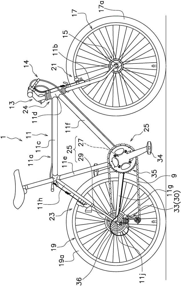
[0035] Such as figure 1 Shown, bicycle 1 comprises vehicle frame 11, handlebar 13, front hub assembly 15, front wheel 17, rear wheel 19, front braking device 21, rear braking device 23, speed change part 30 and driving part 25 (comprising crank assembly 27 and rear hub assembly 29).
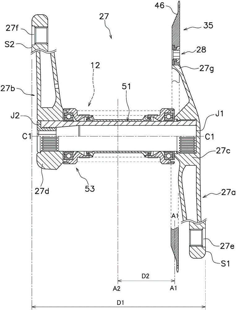
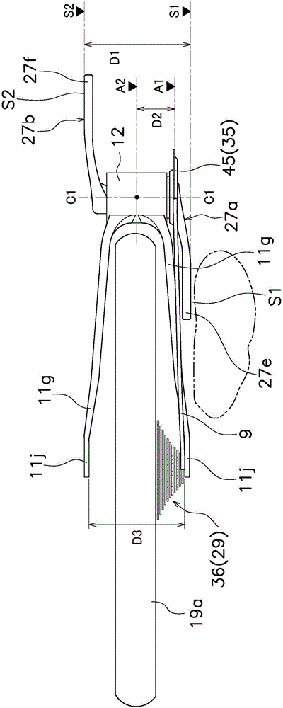
[0036] The frame 11 includes a frame body 11a and a front fork 11b. The frame body 11a includes a top tube 11c, a head tube 11d, a seat tube 11e, a down tube 11f, a pair of chain stays 11g, a pair of seat stays 11h and a bottom bracket 12 (see figure 2 with 3 ). The connecting portion of the seat stay 11h and the chain stay 11g will be described below as a rear end 11j.
[0037] The front fork 11b is rotatably attached to the head pipe 11d of the frame body 11a. The handlebar 13 is fixed to the front fork 11b.
[0038] The front hub assembly 15 is supported on the front fork 11b. The front wheel 17 and the rear wheel 19 are rotatably attached to the front fork 11 b and the rear portion of...
PUM
 Abstract
Description
Claims
Application Information
 - R&D Engineer
- R&D Manager
- IP Professional
- Industry Leading Data Capabilities
- Powerful AI technology
- Patent DNA Extraction
Browse by: Latest US Patents, China's latest patents, Technical Efficacy Thesaurus, Application Domain, Technology Topic, Popular Technical Reports.
© 2024 PatSnap. All rights reserved.Legal|Privacy policy|Modern Slavery Act Transparency Statement|Sitemap|About US| Contact US: help@patsnap.com