injection mold

An injection mold and injection molding technology, applied in the field of molds, can solve problems such as uneven glue feeding, complex structure of injection molds, affecting the appearance quality of injection molding products, etc., and achieve the effect of improving injection molding quality and yield

Inactive Publication Date: 2019-05-14
YULONG COMPUTER TELECOMM SCI (SHENZHEN) CO LTD
View PDF5 Cites 3 Cited by
  • Summary
  • Abstract
  • Description
  • Claims
  • Application Information

AI Technical Summary

Problems solved by technology

However, as the market has higher and higher requirements for the appearance of products, the corresponding injection mold structure is also becoming more and more complex.
The traditional way of using a single hot runner to feed glue into the mold will lead to uneven glue feeding, which will affect the appearance quality of injection molded products

Method used


Image

  • injection mold
  • injection mold
  • injection mold

Examples


Embodiment Construction

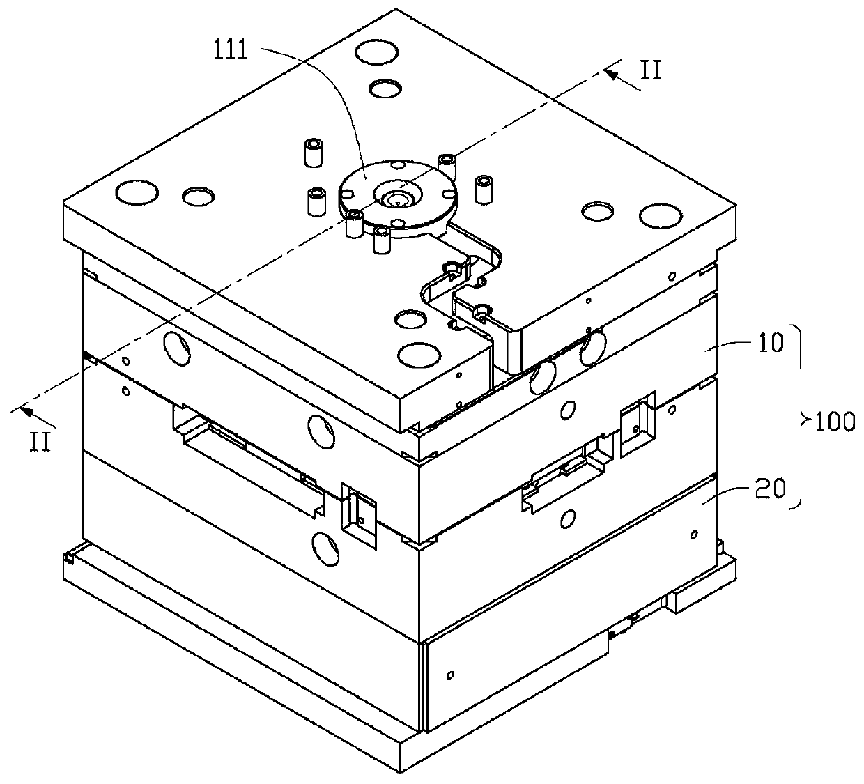
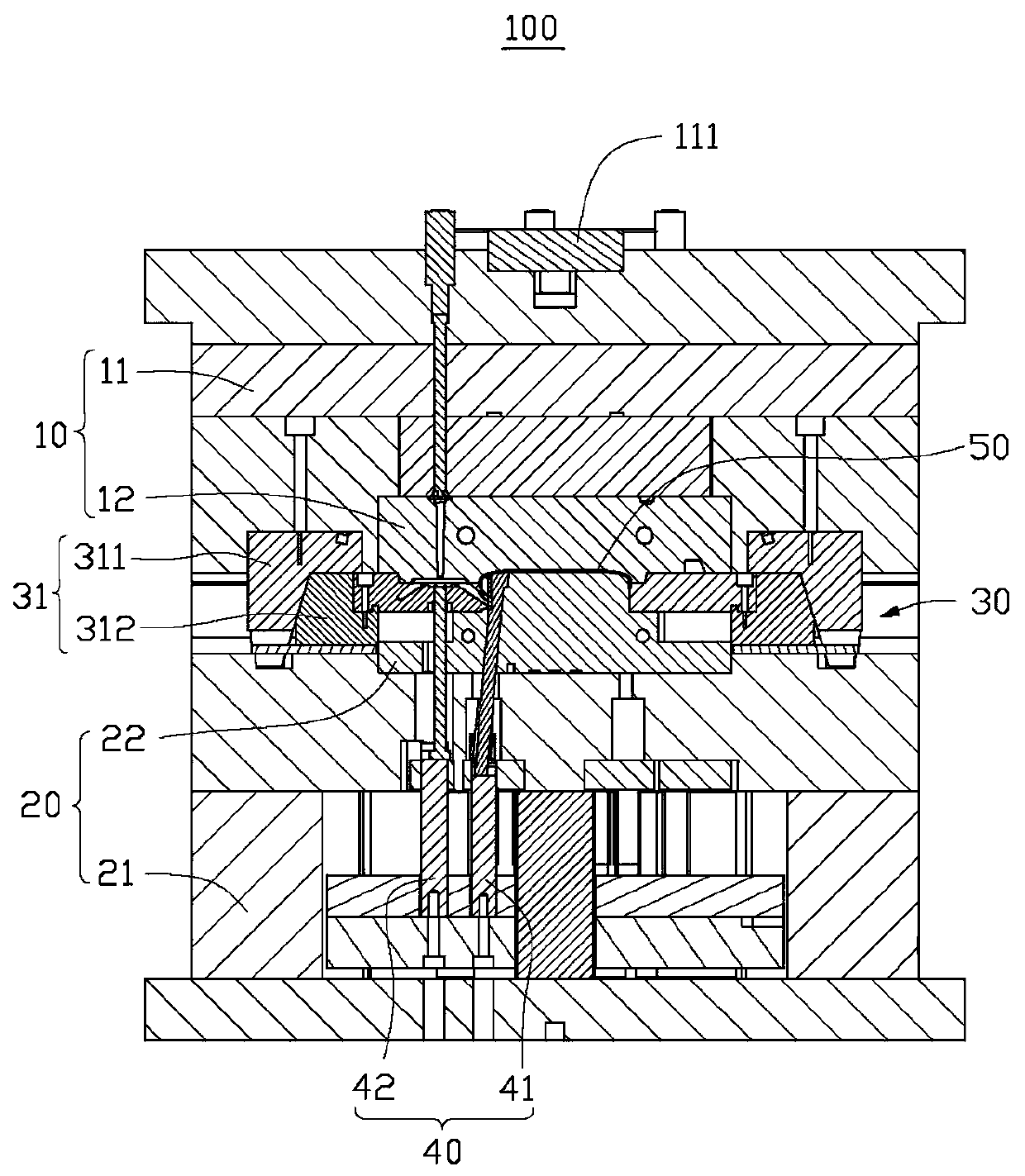
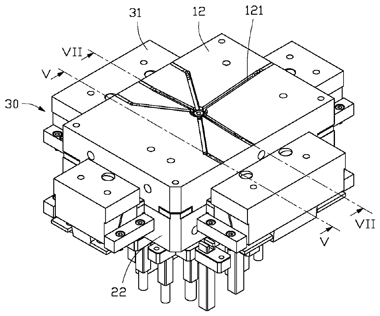
[0016] The technical solutions in the embodiments of the present invention will be clearly and completely described below in conjunction with the accompanying drawings in the embodiments of the present invention. Obviously, the described embodiments are only part of the embodiments of the present invention, not all of them. Based on the implementation manners in the present invention, all other implementation manners obtained by persons of ordinary skill in the art without making creative efforts belong to the scope of protection of the present invention.

[0017] It should be noted that when a component is considered to be "connected" to another component, it may be directly connected to the other component or there may be an intervening component at the same time.

[0018] Unless otherwise defined, all technical and scientific terms used herein have the same meaning as commonly understood by one of ordinary skill in the technical field of the invention. The terminology used ...


PUM


Abstract

The invention provides an injection mold used for injection molding of a workpiece. The injection mold comprises an upper mold body, a lower mold body, a plastic inflow mechanism and a jacking material. The upper mold body comprises an upper mold base and an upper mold core arranged on the upper mold base. The lower mold body comprises a lower mold base and a lower mold core arranged on the lower mold base. The upper mold core and the lower mold core are matched to form a mold cavity. The plastic inflow mechanism comprises a wedge-shaped block, a plastic inflow sliding block and an angle pin. The wedge-shaped block is fixed to the upper mold base, the plastic inflow sliding block is arranged on the lower mold core in a sliding mode and matched with the inclined face of the wedge-shaped block, a plastic inlet is formed in the end, facing the mold cavity, of the plastic inflow sliding block, and therefore the plastic inflow sliding block can inject melted plastic into the mold cavity. The angle pin movably penetrates through the wedge-shaped block and the plastic inflow sliding block, the upper mold base can drive the wedge-shaped block and the angle pin to move away from the lower mold base together, the plastic inflow sliding block moves away from the mold cavity under the effect of the angle pin, and the jacking mechanism is movably arranged in the lower mold body and used for jacking the formed workpiece out of the mold cavity. The appearance quality of the workpiece obtained after injection molding is effectively improved through the injection mold.

Description

technical field [0001] The invention relates to a mold, in particular to an injection mold. Background technique [0002] With the rapid development of the manufacturing industry, injection molding technology has been widely used in mobile terminals, household appliances, automobiles and other industries. The existing injection molding process first injects molten plastic into the mold cavity, and after cooling and solidifying, a product with a specific shape can be formed, and then the product and the residual plastic are ejected through the ejector mechanism. However, as the market has higher and higher requirements on the appearance of products, the corresponding injection mold structure is also becoming more and more complicated. The traditional way of using a single hot runner to feed the mold will lead to uneven glue feeding, which in turn will affect the appearance quality of the injection molded product. Contents of the invention [0003] In view of this, it is n...

Claims


Application Information

Patent Timeline
Patent Type & Authority Patents(China)
IPC IPC(8): B29C45/26B29C45/40B29C45/38
CPCB29C45/2602B29C45/38B29C45/4005
Inventor 杨国柱
Owner YULONG COMPUTER TELECOMM SCI (SHENZHEN) CO LTD
Why Eureka
Try Eureka