Tape reel and tape cartridge having the same

A technology of tape reels and gears, applied in the field of tape cassettes having the tape reels, can solve the problems of data damage to the reliability of recording/playback operations and the like

Inactive Publication Date: 2004-06-02
SONY CORP
View PDF1 Cites 0 Cited by
  • Summary
  • Abstract
  • Description
  • Claims
  • Application Information

AI Technical Summary

Problems solved by technology

Therefore, the data is damaged to cause a problem in the reliability of the recording / playback operation

Method used


Image

  • Tape reel and tape cartridge having the same
  • Tape reel and tape cartridge having the same
  • Tape reel and tape cartridge having the same

Examples


no. 1 example

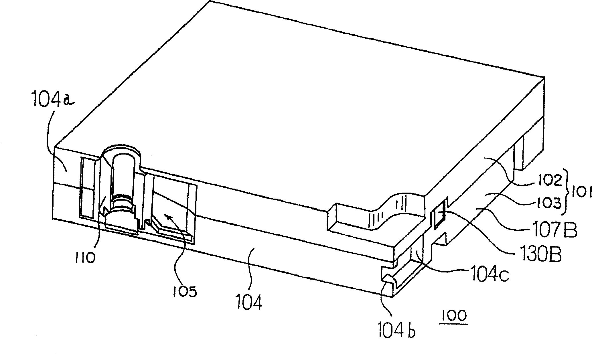
[0049] figure 1 A perspective view showing an external form of a tape cassette according to an embodiment of the present invention.

[0050] Such as figure 1 As shown, the belt box 100 of the present embodiment has a substantially rectangular chamber 101, comprising: an upper cover 102 and a lower cover 103, and an opening 105 arranged in the chamber 101 and the front panel 104 of the chamber 101 The boot block 110.

[0051] The upper cover 102 and the lower cover 103 are formed by injection molding using synthetic resin, such as polycarbonate.

[0052]Moreover, the guide block 110 is connected to one end of the magnetic tape, and the magnetic tape is wound on a tape roll through a guide tape, and the tape roll is accommodated by the chamber 101 (not shown in the figure).

[0053] The front panel 104 of the chamber 101 is the end where the tape cassette is inserted toward the tape drive, and the opening 105 is formed on the chamber 101; figure 1 in the left end), and th...

no. 2 example

[0115] Below, refer to the attached Figure 13 with Figure 14A to Figure 14C A second embodiment of the present invention is described.

[0116] here, Figure 13 A bottom view of the lower flange unit 252 constituting the coil in this embodiment is shown. and Figure 14B with Figure 14C A schematic diagram showing the flow of resin in the main part during injection molding at positions cut by section lines SS31 and SS32, respectively.

[0117] An annular protruding portion 252f engages with an annular opening formed in the lower cover, the opening being disposed at the center of the lower surface of the lower flange unit 252 of this embodiment.

[0118] The protruding portion 252 has a ring clamping gear 252b inside. When the tape cassette is received by the tape receiving unit of the tape drive, the gear 252b meshes with the gear 271a of the rotation shaft provided by the tape drive, and transmits the rotation of the rotation shaft to the tape roll.

[0119] Furtherm...


PUM


Abstract

A tape reel having an improved reliability during high-speed transport of the magnetic tape by improving the molding quality of the flange portion of the tape reel and a tape cartridge having this are disclosed. Reference faces (152v) are provided between a chucking gear (152b) and an outer circumferential rib (152r2) outside the chucking gear (152b), independently of the outer circumferential rib (152r2). Each of the reference faces (152v) is composed two faces: a first rib (152v1) extending circumferentially and a second rib (152v2) extending perpendicularly to the first rib (152v1). The volume of the portions forming the reference faces (152v) is small, and consequently the sink marks after the resin is cured are suppressed, the molding quality of the flange portion (152) is improved. Consequently, the straight-ahead transportability of the magnetic tape during high-speed transport and the reliability of recording / reproduction are both improved..

Description

Technical field: [0001] The present invention relates to a tape cassette containing a tape roll wound with a magnetic tape therein, and more particularly to a tape roll with improved reliability under high-speed motion conditions, and a tape cassette having the tape roll. Background technique [0002] A tape drive is known which records and reproduces information by taking out a magnetic tape as a recording medium from a tape cassette in which there is a single tape reel on which the magnetic tape is wound. Such a tape drive is widely used for system data backup involving a large amount of data such as a computer serving as a server. [0003] As mentioned above, although there are various cassettes having individual tape rolls, for example, there is known a cassette having a leader attached to one end of a magnetic tape and placed in a chamber within the cassette. [0004] When the tape cassette with the guide block is put into the tape drive, the guide block is clamped by ...

Claims


Application Information

Patent Timeline
Patent Type & Authority Applications(China)
IPC IPC(8): G11B23/037G11B23/04G11B23/107G11B23/26
CPCG11B23/043G11B23/048G11B23/26G11B23/044G11B23/107G11B23/037
Inventor 三瓶孝明菊地修一佐佐木一雄樱井美津江千叶仁三
Owner SONY CORP
Why Eureka
Try Eureka