Process variable measurement and local display with multiple ranges

A process variable, range technology, applied in the direction of the indication of the measured value, the indication of the measured value, the measurement of heat, etc.

Active Publication Date: 2017-01-04
ROSEMOUNT INC
View PDF6 Cites 1 Cited by
  • Summary
  • Abstract
  • Description
  • Claims
  • Application Information

AI Technical Summary

Problems solved by technology

This device, although using some electronic components

Method used


Image

  • Process variable measurement and local display with multiple ranges
  • Process variable measurement and local display with multiple ranges
  • Process variable measurement and local display with multiple ranges

Examples


Embodiment Construction

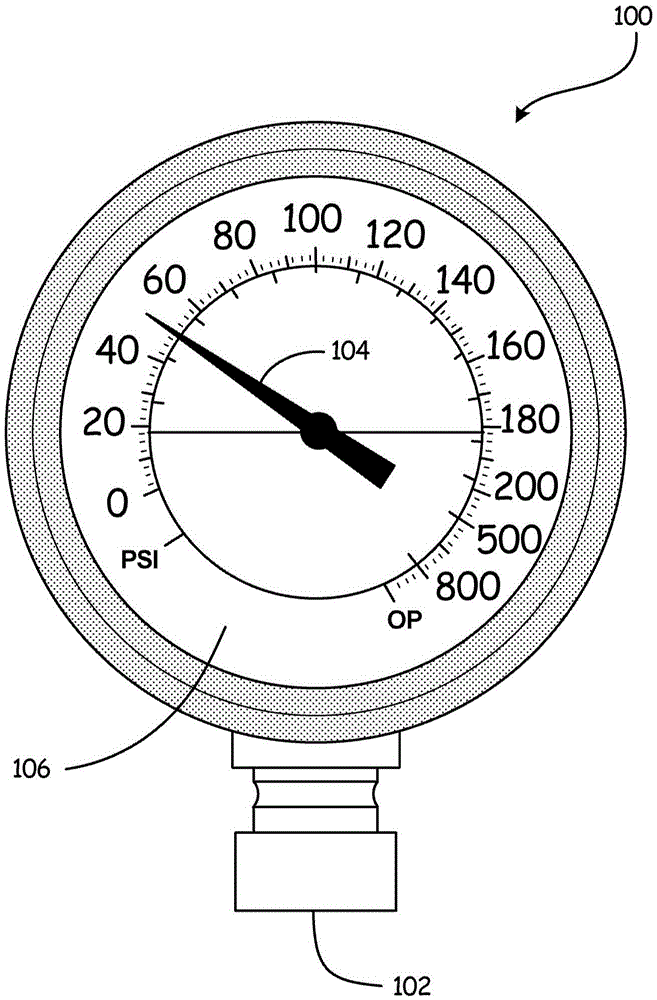
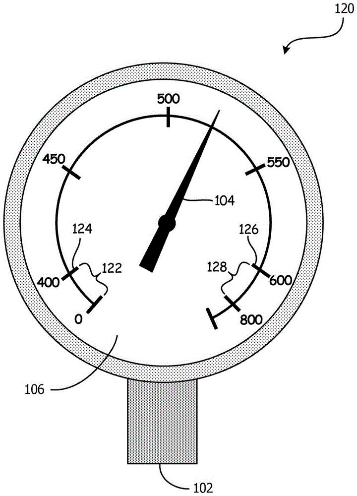
[0013] Measurement and display technologies for mechanical process variables are often limited in their ability to provide any features beyond their core functionality. Conversely, new process devices using electronic components can offer many new features compared to their mechanical equivalents. According to an embodiment of the present invention, a process variable sensing component provided for sensing a process variable with a process variable display device may have a sensing range of the process variable that is substantially in excess of the range desired by the end user. For example, a user ordering a device capable of sensing pressures between 0 and 200 psi may receive a pressure measuring capsule or part capable of accurately sensing pressures between 0 and 800 psi simply because the pressure measuring capsule or The component is the most suitable sensing device for the specified range. However, end-user requirements for an operating range between 0 and 200 psi wil...


PUM


Abstract

A process variable indicator is provided. The process variable indicator includes a process variable sensor having an electrical characteristic that varies with the process variable. Measurement circuitry is coupled to the process variable sensor and is configured to provide an indication relative to the electrical characteristic. A processor is coupled to the measurement circuitry and is configured to compute a process variable based on the indication and determine, among a plurality of ranges, which range the process variable is within. The processor generates a local visual output based on the process variable and the determined range. A method of visually indicating a process variable is also provided.

Description

technical field [0001] The present application relates to process variable indicators and methods of visually indicating process variables. Background technique [0002] Mechanical instruments for measuring and displaying process variables such as pressure or temperature are widely used in industry. These instruments usually do not require any source of electrical power, but instead use mechanical techniques to display their individual process variables. For example, Bourdon tube devices produce movement of a pointer directly in response to pressure changes within the Bourdon tube to which the pointer is exposed. Similarly, a temperature measuring device may have a pointer connected to a bimetallic strip that is sensitive to changes in temperature. These are just two examples of conventional mechanisms that are and will continue to be in process equipment today. By virtue of their mechanical properties, these devices are immune to power failures and are relatively cheap t...

Claims


Application Information

Patent Timeline
IPC IPC(8): G01D7/00G01D7/12G01K1/02G01L19/08
CPCG01D7/00G01D7/12G01K1/02G01K1/024G01K1/028G01L19/083G01L19/086G01L19/16G01D13/26G01L19/10
Inventor 罗伯特·C·黑特克
Owner ROSEMOUNT INC
Why Eureka
Try Eureka