
Antenna and user equipment

A user equipment and antenna technology, applied in the field of communication, can solve the problems of space compression, multi-space, and large space occupied by antennas in the design of mobile phone antennas, and achieve the effect of reducing volume

Active Publication Date: 2017-01-04
ZTE CORP
View PDF5 Cites 6 Cited by
  • Summary
  • Abstract
  • Description
  • Claims
  • Application Information

AI Technical Summary

Problems solved by technology

[0002] While paying attention to the performance and quality of mobile phones, people have increasingly strict requirements on appearance and texture. Among them, ultra-thin and metal-frame mobile phones are more and more popular among consumers in the current market, especially the current fourth-generation mobile communication ( 4G) mobile phones, but in the case of a metal frame, electromagnetic waves are difficult to radiate and be received effectively, the efficiency of the mobile phone antenna will decrease, and the space left for the design of the mobile phone antenna will be further compressed
[0003] Recently, many mobile phone manufacturers have launched metal-frame mobile phones that use the metal frame as a part of the mobile phone antenna, especially some popular 4G mobile phones, but these mobile phone antennas based on metal frames are difficult to cover the long-term evolution (LTE) All frequency bands of the system, at the same time, it is often necessary to introduce additional tunable switch modules, antenna stub units, and electrical connectors on the basis of the metal frame
[0004] The problem caused by this is that it takes up more space, and at the same time, additional tuning switches, antenna stub units, and electrical connectors are introduced, which will inevitably increase the design cost and complexity.
[0005] For the problem of the large space occupied by the antenna in the related art, no effective solution has been proposed at present

Method used


Image

  • Antenna and user equipment
  • Antenna and user equipment
  • Antenna and user equipment

Examples


Embodiment Construction

[0033] Hereinafter, the present invention will be described in detail with reference to the drawings and examples. It should be noted that, in the case of no conflict, the embodiments in the present application and the features in the embodiments can be combined with each other.

[0034] Additional features and advantages of the invention will be set forth in the description which follows, and in part will be apparent from the description, or may be learned by practice of the invention. The objectives and other advantages of the invention may be realized and attained by the structure particularly pointed out in the written description and claims hereof as well as the appended drawings.

[0035] In order to enable those skilled in the art to better understand the solutions of the present invention, the following will clearly and completely describe the technical solutions in the embodiments of the present invention in conjunction with the drawings in the embodiments of the pres...


PUM


Abstract

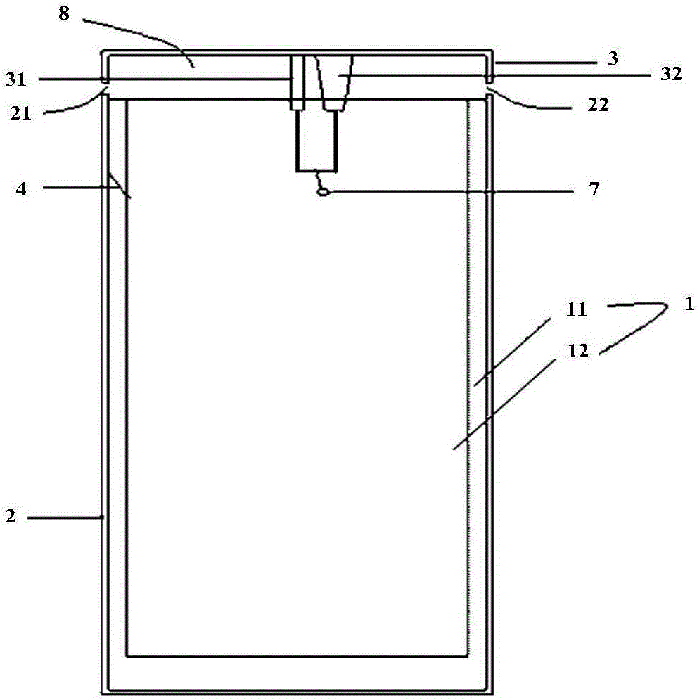
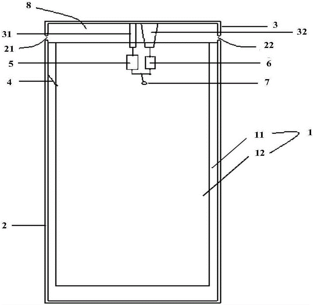
The invention provides an antenna and a piece of user equipment. The antenna comprises a mainboard PCB 1, a metal frame 2, an antenna radiating unit 3, a first feeding branch unit 31, a second feeding branch unit 32, a grounding element 4, a feeding point 7 and a clearance area 8. The mainboard PCB 1 is connected to the metal frame 2 through the grounding element 4. The antenna radiating unit 3 is provided in the clearance area 8 located on the upper side of the mainboard PCB 1. The metal frame 2 and the antenna radiating unit 3 are arranged around the user equipment to form a border of the user equipment. A first slit 21 and a second slit 22 are provided between the metal frame 2 and the antenna radiating unit 3. The feeding point 7 is connected to the antenna radiating unit 3 through the first feeding branch unit 31 and the second feeding branch unit 32. By the present invention, the problem of large space occupied by the antenna is solved, and the volume occupied by the antenna is reduced.

Description

technical field [0001] The present invention relates to the communication field, in particular, to an antenna and user equipment. Background technique [0002] While paying attention to the performance and quality of mobile phones, people have increasingly strict requirements on appearance and texture. Among them, ultra-thin and metal-frame mobile phones are more and more popular among consumers in the current market, especially the current fourth-generation mobile communication ( 4G) mobile phones, but in the case of a metal frame, it is difficult for electromagnetic waves to radiate and be received effectively, the efficiency of the mobile phone antenna will decrease, and the space left for the design of the mobile phone antenna will be further compressed. [0003] Recently, many mobile phone manufacturers have launched metal-frame mobile phones that use the metal frame as a part of the mobile phone antenna, especially some popular 4G mobile phones, but these mobile phone ...

Claims


Application Information

Patent Timeline
Patent Type & Authority Applications(China)
IPC IPC(8): H01Q1/38H01Q1/50H01Q1/24
CPCH01Q1/243H01Q9/0407H01Q5/50H01Q5/10H01Q1/38H04M1/0277H04M1/0283H01Q5/335H01Q5/371
Inventor 程孝奇
Owner ZTE CORP
Learn More