
Antenna of smart watch and smart watch

A smart watch and antenna technology, applied in the field of smart watches, can solve the problems that it is difficult to meet the miniaturization and lightweight design requirements of wearable devices, achieve the effect of multi-mode broadband coverage and solve design conflicts

Active Publication Date: 2019-04-05
QINGDAO HISENSE MOBILE COMM TECH CO LTD
View PDF5 Cites 0 Cited by
  • Summary
  • Abstract
  • Description
  • Claims
  • Application Information

AI Technical Summary

Problems solved by technology

However, the current design of mobile phone antennas is difficult to meet the miniaturization and lightweight design requirements of wearable devices. At the same time, the metallized appearance of wearable devices also poses a greater technical challenge to antenna design.

Method used


Image

  • Antenna of smart watch and smart watch
  • Antenna of smart watch and smart watch
  • Antenna of smart watch and smart watch

Examples


Embodiment 1

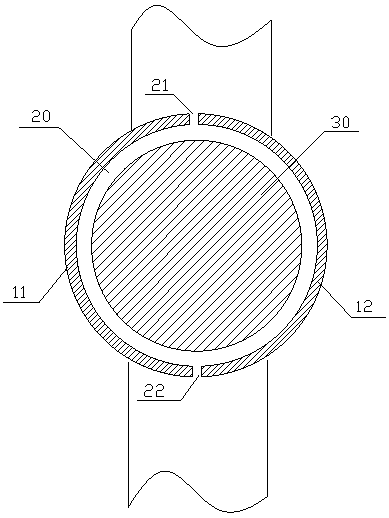
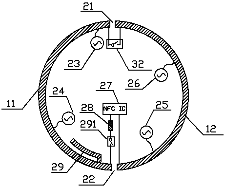
[0022] Embodiment one, such as figure 2 As shown, the antenna design of this embodiment adopts the method of opening two slits (the first slit 21 and the second slit 22) on the metal frame of the smart watch, and divides the metal frame into two independent parts, that is, the second A section of metal frame 11 and a second section of metal frame 12 . Use the first section of the metal frame 11 as the main antenna, that is, the mobile communication antenna, and connect to the mobile communication module, such as 2G (such as GSM B5, B8, CDMA B5, WCDMA B5, etc.), 3G (such as B26, B20, etc.), 4G LTE module etc., and the antenna auxiliary wiring 29 is designed to be connected to the first section of the metal frame 11 and at a position close to the second slit 22, for example, at a position 0.5cm-1cm away from the second slit. The antenna auxiliary wiring 29 is arranged inside the smart watch, and its shape and length can be specifically determined according to signal radiation ...

Embodiment 2

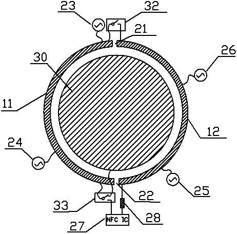
[0031] Embodiment two, such as image 3 As shown, the antenna design of this embodiment adopts the method of opening two slits (the first slit 21 and the second slit 22) on the metal frame of the smart watch, and divides an originally continuous ring-shaped metal frame into independent of the two paragraphs, such as image 3 The first section of the metal frame 11 and the second section of the metal frame 12. Among them, the first metal frame 11 can be used as the main antenna of the smart watch, that is, the mobile communication antenna, connected to the mobile communication module inside the smart watch, such as 2G, 3G, 4GLTE modules, etc., to realize the mobile phone function of the smart watch. The second metal frame 12 can be used as the GPS and WiFi antenna of the smart watch, and connects the GPS module and the WiFi module inside the smart watch to realize the GPS function and the WiFi function of the smart watch.

[0032] Compared with Embodiment 1, the difference of...


PUM


Abstract

The invention discloses an antenna of an intelligent watch, and an intelligent watch. The intelligent watch is provided with a metal frame, the metal frame is provided with two kerfs, the metal frame is divided into two independent segments through the two kerfs, and one segment of the metal frame serves as a mobile communication antenna for connection with a mobile communication module; the second segment of the metal frame serves as a GPS and a WiFi antenna for connection with a GPS module and a WiFi module; and a gating switch is connected at one of the kerfs, and the two segments of the metal frame are connected together through the gating switch so as to form an NFC antenna. According to the invention, an open gap design is employed for the intelligent watch of a metal structure, the metal frame of the intelligent watch is segmented into the two independent segments so as to form two segments of antenna arms, an all-network antenna of the intelligent watch is formed, and through reconstruction of the two segments of antenna arms, the NFC antenna is formed, such that integration of the antenna design of the intelligent watch and compatibility between antenna parts and structure parts are realized, and multimode wideband coverage of the antenna is realized.

Description

technical field [0001] The invention belongs to the technical field of smart watches, and in particular relates to an antenna structure design that can be applied to a smart watch with a metal frame. Background technique [0002] With the rapid development of smart mobile terminal technology, the compatible performance of mobile terminals has been continuously enriched, and the form of mobile terminals has also expanded from the initial mobile phone to wearable devices. With the good market prospects and popularization of wearable devices, more and more functions are compatible with them. In addition to the functions of call, data link, NFC and other functions of traditional communication devices, their functions are also being used by more and more Compatible with wearable devices, more and more corresponding antenna and coil devices are implanted into wearable devices to achieve communication compatibility. However, the current mobile phone antenna design scheme is diffic...

Claims


Application Information

Patent Timeline
Patent Type & Authority Patents(China)
IPC IPC(8): H01Q1/44G04B47/00
CPCG04B47/00H01Q1/44
Inventor 李勇胡育根赵鹏
Owner QINGDAO HISENSE MOBILE COMM TECH CO LTD
Learn More