
Monitoring system and device based on unmanned aerial vehicle

A monitoring system and unmanned aerial vehicle technology, applied in the direction of control/adjustment system, closed-circuit television system, attitude control, etc., can solve the limited range of monitoring system monitoring, monitoring system monitoring dead angle, monitoring system equipment cost, installation cost and maintenance cost increase etc.

Inactive Publication Date: 2017-01-11
BEIJING QIHOO TECH CO LTD +1
View PDF6 Cites 28 Cited by
  • Summary
  • Abstract
  • Description
  • Claims
  • Application Information

AI Technical Summary

Problems solved by technology

When monitoring moving objects or people, it is usually necessary to set up multiple front-end monitoring equipment, and at the same time be equipped with corresponding transmission equipment, back-end storage, control and display equipment. When the moving target is monitored, a large number of front-end monitoring devices need to be installed to realize the relay monitoring of the moving target, so the equipment cost, installation cost and maintenance cost of the monitoring system will increase greatly; in addition, when the monitoring system cannot be installed Some areas of the front-end monitoring equipment of the system cannot be monitored by the traditional monitoring system; furthermore, due to the limited front-end monitoring equipment, the range that the monitoring system can monitor is limited, and due to the limitations of the front-end monitoring equipment, it is inevitable. There is a monitoring dead angle within the monitoring range of the monitoring system

Method used


Image

  • Monitoring system and device based on unmanned aerial vehicle
  • Monitoring system and device based on unmanned aerial vehicle
  • Monitoring system and device based on unmanned aerial vehicle

Examples


Embodiment Construction

[0075] The present invention will be further described below with reference to the accompanying drawings and exemplary embodiments, in which the same reference numerals in the accompanying drawings all refer to the same components. In addition, if a detailed description of the known technology is unnecessary to show the features of the present invention, it will be omitted.

[0076] It should be noted that the terms "first" and "second" in the specification and claims of the present invention and the above-mentioned drawings are used to distinguish similar objects, and not necessarily used to describe a specific sequence or sequence. It should be understood that the data used in this way can be interchanged under appropriate circumstances so that the embodiments described herein can be implemented in a sequence other than those illustrated or described herein. In addition, the terms "including" and "having" and any variations of them are intended to cover non-exclusive inclusions...


PUM


Abstract

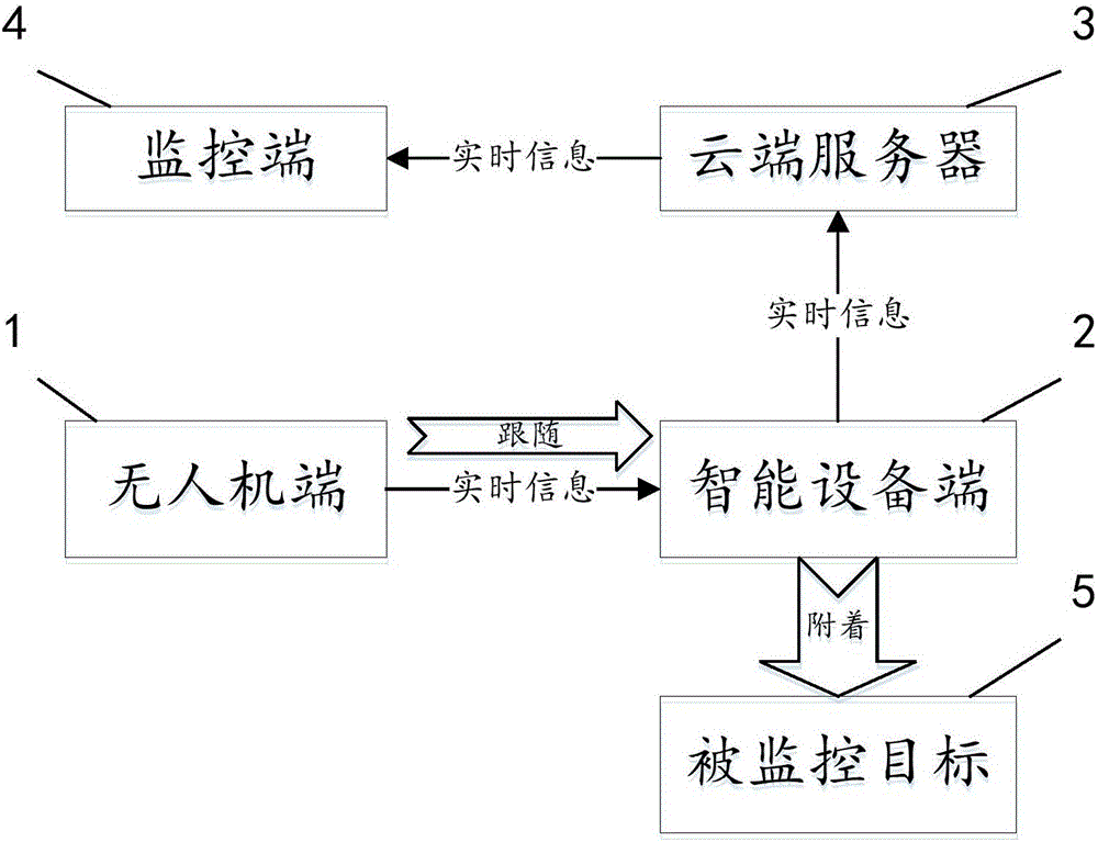
The invention discloses a monitoring system based on an unmanned aerial vehicle, comprising an unmanned aerial vehicle terminal, an intelligent equipment terminal, a cloud terminal server and a monitoring terminal, wherein the intelligent equipment terminal is adhered to the monitored target, a first communication module and a processor module are arranged in the intelligent equipment terminal, the unmanned aerial vehicle terminal is connected with the intelligent equipment terminal, a tracking module is arranged in the unmanned aerial vehicle terminal, the unmanned aerial vehicle terminal can fly along the intelligent equipment terminal by the tracking module. The internal shooting module is used for obtaining the real-time video information of the monitored target and the surroundings, a second inner communication module is used for communicating with the information of the first communication module, the intelligent equipment terminal uploads the real-time information of the monitored target to the cloud terminal server by the first communication module, and the monitoring terminal can obtain the real-time information from the cloud terminal server. The unmanned aerial vehicle in the invention is used as the front-end monitoring equipment so as to solve the problems of limited monitoring range, high monitoring cost and monitoring dead angle existing in the traditional monitoring system.

Description

【Technical Field】 [0001] The invention relates to the field of monitoring, in particular to a monitoring system based on UAV 【Background technique】 [0002] Nowadays, the middle-aged and young people in urban life often have no time to take care of young children because of their busy work. At this time, people usually take their parents to the city to help take care of the young children. However, most parents are not well-educated or have insufficient urban life experience. When they first come to live in an unfamiliar environment for a period of time, they often have various troubles because they do not understand city life. What's more, when some old people are taking children out to play, they will encounter criminals who abduct and traffic children and fall into the trap of criminals, leading to incidents of abduction of young children. The ultimate reason for such incidents is that parents of young children cannot accompany the elderly and young children. At this time, mo...

Claims


Application Information

Patent Timeline
IPC IPC(8): G05D1/08G05D1/10H04N7/18
CPCH04N7/185G05D1/0808G05D1/101
Inventor 任毫亮
Owner BEIJING QIHOO TECH CO LTD
Learn More