A deicer for power wires and cables

A deicer and cable technology, applied in the installation of cables, electrical components, overhead installation, etc., can solve the problems of increased burden on utility poles, electric shock, disasters of pedestrians and residents’ houses, etc.

Active Publication Date: 2018-10-12
枣庄市昌恒台装饰新材料科技有限公司
View PDF9 Cites 0 Cited by
  • Summary
  • Abstract
  • Description
  • Claims
  • Application Information

AI Technical Summary

Problems solved by technology

[0002] With the continuous improvement of living standards, it also further promotes the continuous development of the power industry. In the current power industry, cables are one of the indispensable power transmission equipment, so that the cables can be used to transmit electric energy thousands of miles away. To thousands of households, so as to achieve the purpose of power transmission. In the current cable laying process, most of the cables are laid at high altitudes using electric poles to prevent electric shock damage caused by cables to the human body. In winter, Due to the cold weather, a large amount of snow will accumulate on the cable, which will cause a large number of ice cubes to form on the cable over time. Although the accumulation of ice cubes will not affect the power transmission, there are still the following problems: when a large amount of ice After the blocks gather on the cable, it will further increase the weight of the cable, which will cause the cable to break over time. When the cable breaks, it will cause the cable to contact the ground. It will further cause the occurrence of electric shock problems, which will cause certain dangers to pedestrians, and when a large number of ice cubes on the cables are gathered, since the cables on the utility poles will be arranged in multiple rows, it will cause a certain danger to pedestrians. The utility poles add a certain burden. When more ice cubes gather on the cables, there will be a danger of tilting and breaking the utility poles, which will further cause devastating disasters to pedestrians and nearby residential buildings.

Method used


Image

  • A deicer for power wires and cables
  • A deicer for power wires and cables
  • A deicer for power wires and cables

Examples


Embodiment Construction

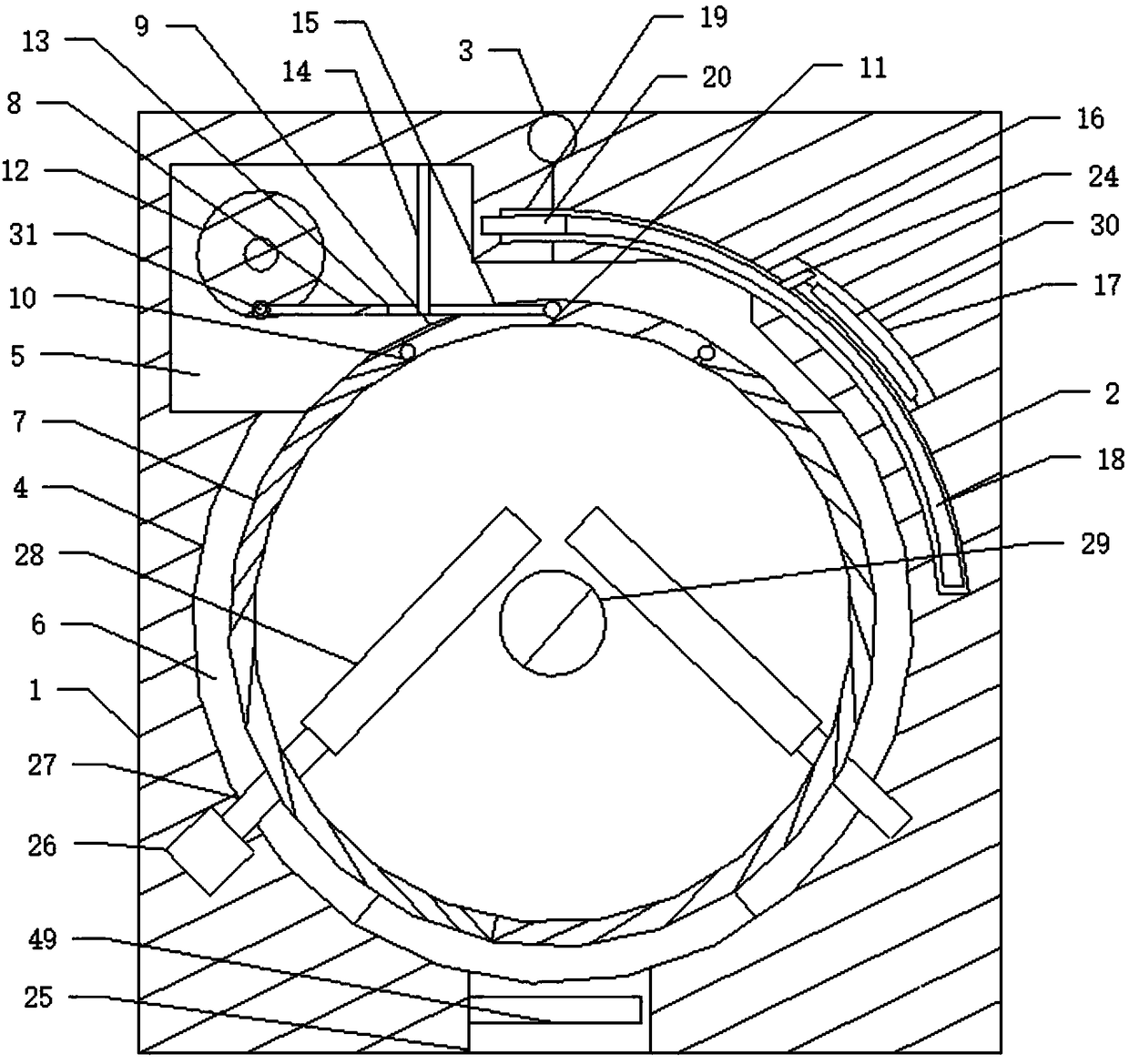
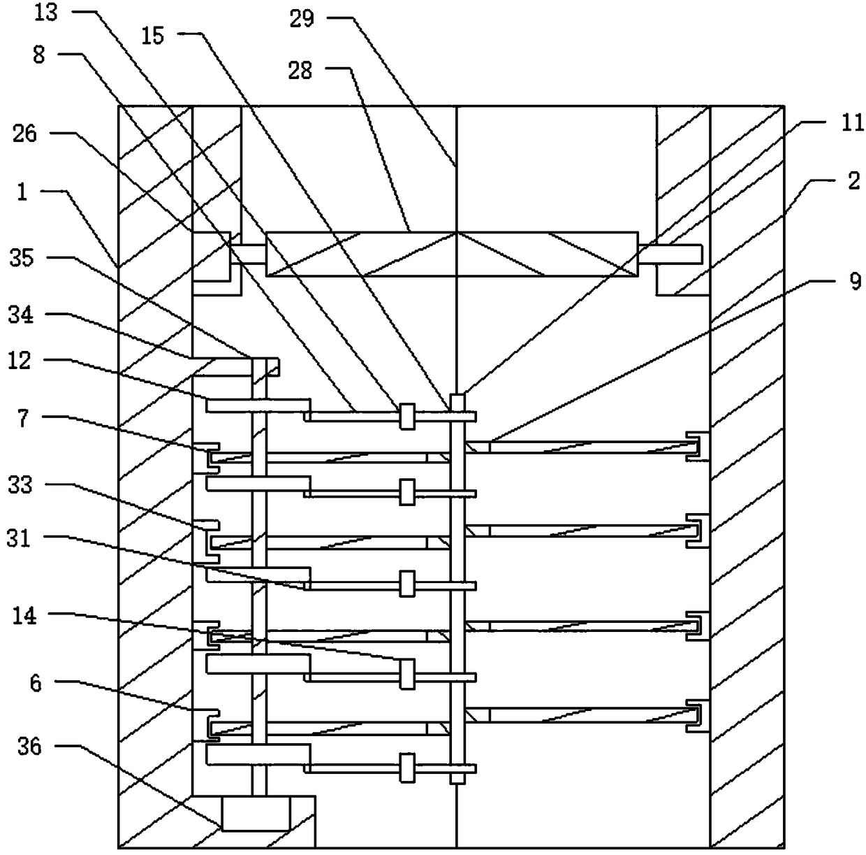
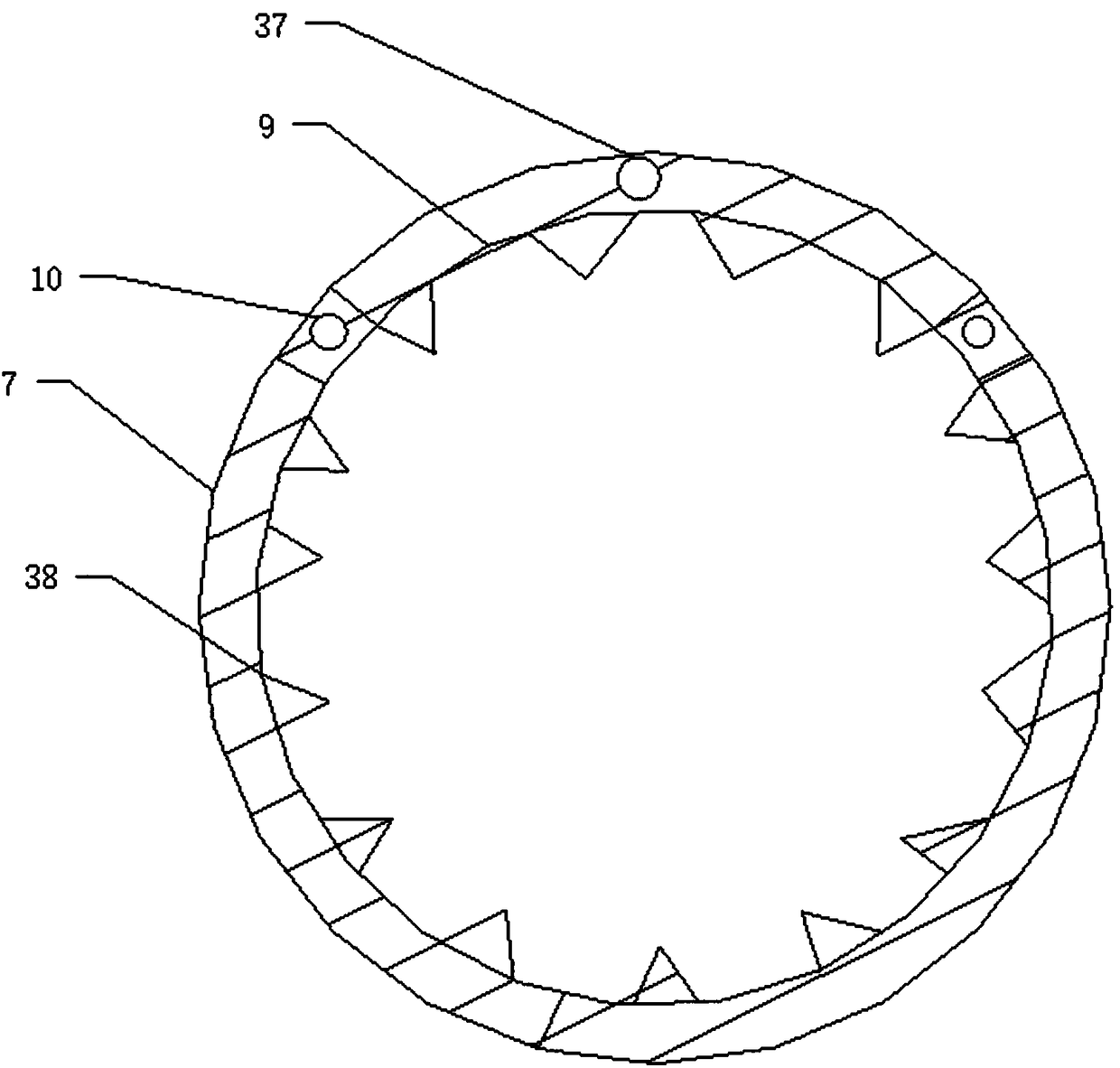
[0028] Such as Figure 1 to Figure 8 As shown, a power wire and cable deicer includes a cable 29 on which a first body 1 and a second body 2 are arranged, and the first body 1 and the second body 2 Correspondingly connected by a first connecting shaft 3, the first body 1 and the second body 2 are respectively provided with a semicircular deicing groove 4, and the deicing groove 4 is connected to the cable 29. Correspondingly, the first body 1 is provided with a power chamber 5 corresponding to the deicing tank 4, and the power chamber 5 is provided with a second rotating shaft 35 driven by a second motor 36, and the second rotating shaft 35 is provided with a row of driving runners 12, each of which includes a first drive shaft 8 that rotates on the driving runners 12, and is also provided with a row of The deicing groove 4 corresponds to the connecting ice blade 9, and the two ends of the connecting ice blade 9 are respectively connected to a corresponding deicing blade disc...


PUM


Abstract

The invention discloses a power wire and cable deicer. The power wire and cable deicer includes a cable; the cable is provided with a first machine body and a second machine body; the first machine body is correspondingly connected with the second machine body through a first connection shaft; each of the first machine body and the second machine body is provided with a semi-circular deicing groove; a row of connecting ice blades corresponding to a corresponding deicing groove is arranged in the deicing groove; two ends of each connecting ice blade are respectively connected with two deicing blade disc which are corresponding to each other; the deicing blade discs are semicircular and are corresponding to the cable; and in the rotation process of driving wheels, the deicing blade discs can be driven to rotate in a reciprocating manner in the deicing grooves, so that ice blocks on the cable can be cut and rubbed in the reciprocating rotation process of the deicing blade discs, and therefore, deicing can be realized, and cable fracture caused by the accumulation of a large number of ice blocks on the cable can be prevented.

Description

technical field [0001] The invention relates to a deicing device, in particular to a power wire and cable deicer, in particular to a power wire and cable deicer capable of sliding on the wire and cable. Background technique [0002] With the continuous improvement of living standards, it also further promotes the continuous development of the power industry. In the current power industry, cables are one of the indispensable power transmission equipment, so that the cables can be used to transmit electric energy thousands of miles away. To thousands of households, so as to achieve the purpose of power transmission. In the current cable laying process, most of the cables are laid at high altitudes using electric poles to prevent electric shock damage caused by cables to the human body. In winter, Due to the cold weather, a large amount of snow will accumulate on the cable, which will cause a large number of ice cubes to form on the cable over time. Although the accumulation of...

Claims


Application Information

Patent Timeline
Patent Type & Authority Patents(China)
IPC IPC(8): H02G7/16
CPCH02G7/16
Inventor 左常亮
Owner 枣庄市昌恒台装饰新材料科技有限公司
Why Eureka
Try Eureka