

InP (indium phosphide) wafer thinning and polishing method and chemical corrosion device
A technology of thinning polishing and chemical corrosion, which can be used in grinding devices, grinding/polishing equipment, machine tools with surface polishing, etc., and can solve the problems of low production efficiency, slow thinning rate, and increased surface scratches.
- Summary
- Abstract
- Description
- Claims
- Application Information
AI Technical Summary
Benefits of technology
Problems solved by technology
Method used
Image

Examples
Embodiment Construction
[0025] The present invention will be described in detail below in conjunction with the implementations shown in the drawings, but it should be noted that these implementations are not limitations of the present invention, and those of ordinary skill in the art based on the functions, methods, or structural changes made by these implementations Equivalent transformations or substitutions all fall within the protection scope of the present invention.
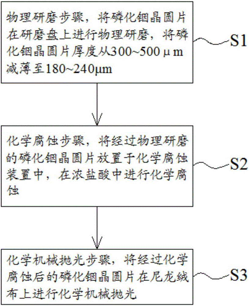
[0026] Such as figure 1 As shown, the method for thinning and polishing the indium phosphide wafer of the present invention comprises the following steps:
[0027] S1, the physical grinding step, the indium phosphide wafer is physically ground on a grinding disc, and the thickness of the indium phosphide wafer is reduced from 300-500 μm to 180-240 μm.
[0028] Specifically, when the indium phosphide wafer is physically ground on a grinding disc, a grinding solution whose main component is alumina powder is used for grinding. Pref...
PUM
 Abstract
Description
Claims
Application Information