Camera system, blur correction method therefor, camera body and interchangeable lens

A technology for shake correction and camera, which is applied in the field of camera systems to achieve the effects of improving the performance of shake correction and expanding the range of shake correction.

Active Publication Date: 2017-01-25
OM DIGITAL SOLUTIONS CORP
View PDF6 Cites 19 Cited by
  • Summary
  • Abstract
  • Description
  • Claims
  • Application Information

AI Technical Summary

Problems solved by technology

[0013] A first aspect of the present invention is a camera system including an interchangeable lens and a camera body configured to allow detachable attachment of the interchangeable lens, wherein the camera body has a shake correction unit that implements corrections for a plurality of rotation directions. Shake correction, the plurality of rotation directions include: a roll direction, which is a rotation direction whose rotation axis is the optical axis of the interchangeable lens mounted on the camera body; a pitch direction, which is a rotation direction perpendicular to the optical axis The axis is the rotation direction of the rotation axis; the yaw direction is the rotation direction with the axis perpendicular to both the optical axis and the axis perpendicular to the optical axis as the rotation axis; the determination unit determines the whether the interchangeable lens on the camera body can implement shake correction for the pitch direction and the yaw direction; the roll shake correction range setting unit, which is determined by the determination unit as being installed on the camera body In a case where the interchangeable lens cannot perform shake correction in the pitch direction and shake correction in the yaw direction, the shake correction unit performs shake correction in the roll direction. The shake correction range is set as the first shake correction range, or the determination unit determines that the interchangeable lens mounted on the camera body can perform shake correction in the pitch direction and the yaw direction. In the case of the shake correction, the shake correction range in the roll direction when the shake correction unit performs shake correction in the roll direction is set to a second shake correction range equal to or larger than the first shake correction range a pitch and yaw shake correction range setting section, which sets the shake correction range by the shake acco

Method used


Image

  • Camera system, blur correction method therefor, camera body and interchangeable lens
  • Camera system, blur correction method therefor, camera body and interchangeable lens
  • Camera system, blur correction method therefor, camera body and interchangeable lens

Examples


no. 1 Embodiment approach

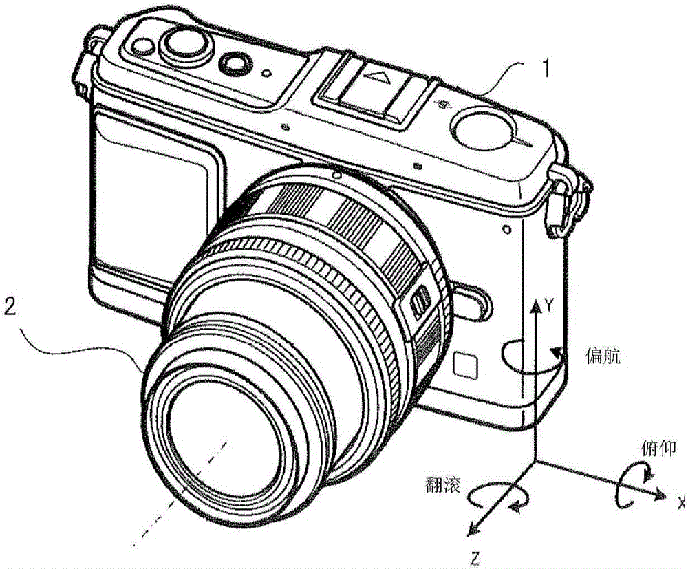
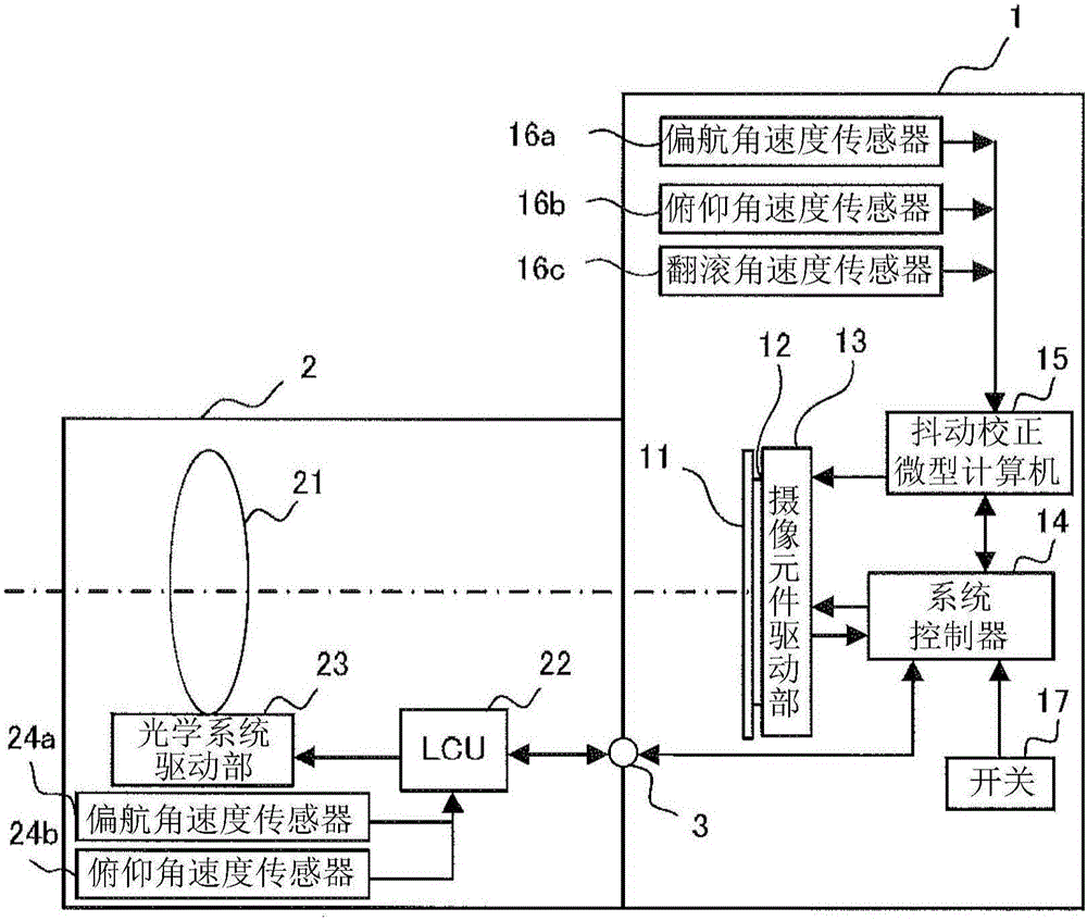
[0068] figure 2 It is a diagram showing a configuration example of the camera system according to the first embodiment of the present invention.

[0069] Such as figure 2 As shown, the camera system of this embodiment has a structure in which an interchangeable lens 2 is attached to a camera body 1 . In addition, the camera body 1 is configured such that an interchangeable lens 2 can be detachably attached. The interchangeable lens 2 is attached to the camera body 1 by fitting a not-shown lens mount connection portion provided on the interchangeable lens 2 and a not-shown body mount connection portion provided on the camera body 1 . . As a result, the interchangeable lens 2 is fixed to the camera body 1 , and the terminals provided at the mounting connection parts are also electrically connected to each other, enabling communication between the camera body 1 and the interchangeable lens 2 via the contacts 3 .

[0070] The camera body 1 includes a focal plane shutter 11, ...

no. 2 Embodiment approach

[0193]The camera system according to the second embodiment of the present invention differs from the camera system according to the first embodiment in the method of determining the roll correction range length. More specifically, in the first embodiment, the roll correction range length is determined regardless of the focal length of the optical system 21, whereas in the second embodiment, the length of the roll correction range can be changed according to the focal length of the optical system 21. Determines the roll correction range length.

[0194] Figure 18 It is a diagram showing a configuration example of the correction range length calculation unit 156 of the second embodiment.

[0195] Such as Figure 18 As shown, regarding the correction range length calculation unit 156 of the second embodiment, in addition to the information on whether the interchangeable lens 2 attached to the camera body 1 is an interchangeable lens capable of performing shake correction in th...

no. 3 Embodiment approach

[0220] The camera system according to the third embodiment of the present invention differs from the camera system according to the first embodiment in the determination method of the roll correction range length. More specifically, in the first embodiment, the length of the roll correction range is determined depending on whether the interchangeable lens 2 attached to the camera body 1 can perform shake correction in the pitch direction and the yaw direction. In contrast, in the third embodiment, roll is determined based on whether the interchangeable lens 2 attached to the camera body 1 is an interchangeable lens capable of correcting camera shake in the pitch direction and the yaw direction, and whether the camera shake in the roll direction is large. Calibration range length.

[0221] Figure 23 It is a diagram showing a configuration example of the shake correction microcomputer 15 according to the third embodiment.

[0222] Such as Figure 23 As shown, in the third em...


PUM


Abstract

A camera system including an interchangeable lens and a camera body, in which the camera body includes: a Roll blur correction range setting unit that sets a blur correction range in Roll directions of the camera body to be theta 1 when the interchangeable lens mounted on the camera body cannot perform blur correction (in the Pitch directions and the Yaw directions) or that sets the range to be theta 2 (greater than or equal to theta 1) when the interchangeable lens can perform blur correction; a Pitch-Yaw blur correction range setting unit that sets blur correction ranges in the Pitch and Yaw directions of the camera on the basis of the set blur correction range in the Roll direction; and a blur correction ratio calculation unit that calculates a blur correction ratio of each of the interchangeable lens and the camera body when both of them perform blur correction.

Description

technical field [0001] The present invention relates to a camera system including an interchangeable lens and a camera body equipped with an image shake correction function for correcting image quality deterioration caused by hand shake, and a camera shake correction method for the camera system. Background technique [0002] In recent years, cameras equipped with a hand-shake correction function have become widespread, and it is possible to take good images free from image shake even without paying special attention to hand-held shooting. [0003] In addition, there is an interchangeable-lens camera in which a photographic lens can be replaced according to photographic purposes. In such a camera system, the aforementioned camera shake correction function may be mounted on an interchangeable lens or a camera body. [0004] When an interchangeable lens is equipped with a hand shake correction function, the interchangeable lens is equipped with a sensor that detects shake, an...

Claims


Application Information

Patent Timeline
IPC IPC(8): G03B5/00H04N5/225
CPCG03B5/00H04N23/50H04N23/663H04N23/6812H04N23/687G02B27/646G03B17/14G03B2205/0007
Inventor 古谷野贤人
Owner OM DIGITAL SOLUTIONS CORP
Why Eureka
Try Eureka