Supercharge Your Innovation With Domain-Expert AI Agents!

Clamping jaw

A technology of clamping jaws and chucks, applied in the directions of chucks, manipulators, manufacturing tools, etc., can solve the problems of low machining accuracy of milling machines, low structural precision of clamping jaws, and defective products.

Inactive Publication Date: 2017-02-01
ZHEJIANG ZHONGXIAN ELECTRONICS TECH CO LTD
View PDF7 Cites 2 Cited by
  • Summary
  • Abstract
  • Description
  • Claims
  • Application Information

AI Technical Summary

Problems solved by technology

[0003] The chute on the top of the base is processed by a milling machine, which cannot be processed by a grinding machine with high machining accuracy. The milling machine has the problem of low machining accuracy, and, during the assembly process, the gap between the air gripper and the base cannot be adjusted. Adjustment, resulting in low precision of the gripper structure, and in the case of a large size difference between the air gripper and the base, it is easy to cause defective products

Method used


Image

  • Clamping jaw
  • Clamping jaw
  • Clamping jaw

Examples


Embodiment Construction

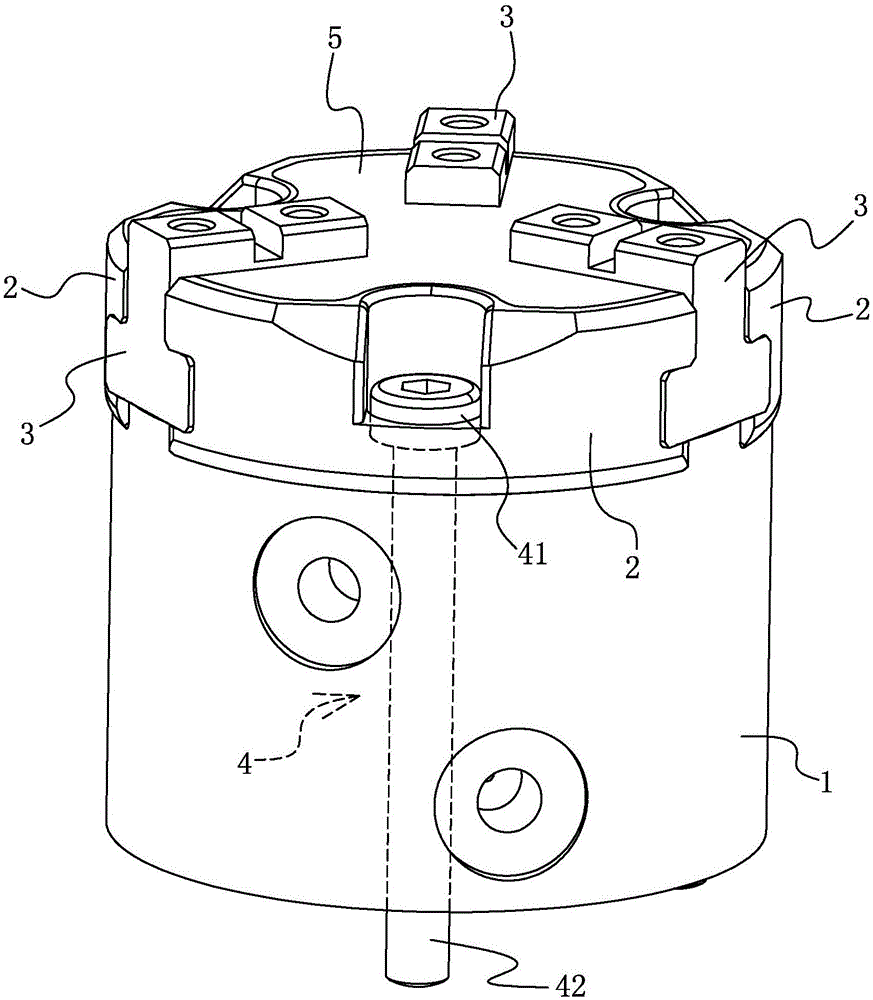
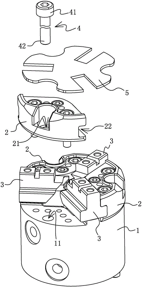
[0016] Such as figure 1 and figure 2 As shown, the jaw in this embodiment includes a body 1 and a base 2 fixedly connected to the body 1 . The number of the base 2 is three, and the base 2 has three clamping heads 3 which are movable. Between two adjacent bases 2, there is a groove 22 for the sliding of the chuck 3. There is a distance between the groove and the bottom surface of the base, and the grooves on the two adjacent bases form a chute for the sliding of the chuck. , The chuck 3 is located in the groove 22 . Three bases 2 and three clamping heads 3 are arranged at intervals and distributed in a circle. The top of the base 2 is provided with a cover plate 5 for dustproofing.

[0017] Of course, as other alternatives, the number of bases 2 and chucks 3 can be two or more.

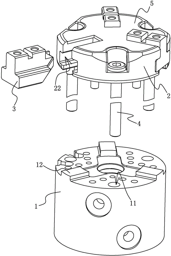
[0018] Such as image 3 As shown, the upper side of the body has the same number of protrusions as the base, the upper side of the protrusion is adjacent to the lower side of the chuck, and the...


PUM


Abstract

The invention discloses a clamping jaw, and belongs to the technical field of clamping jaws, and the clamping arm is used for solving the problem that precision of an existing clamping jaw is not high. The clamping jaw comprises a body and at least two pedestals which are fixedly arranged at the upper side of the body; a clamping head is arranged between every two adjacent pedestals; the pedestals and the clamping heads are circumferentially distributed in a spaced manner; grooves are formed in adjacent side walls between every two adjacent pedestals; spacing exists between the grooves and the bottom surfaces of the pedestals; the grooves in every two adjacent pedestals form a slide slot for allowing the clamping heads to slide; bumps which are as many as the pedestals are arranged at the upper side of the body; the upper side surfaces of the bumps are adjacent to the lower side surfaces of the clamping heads; and two side surfaces of each bump are separately adjacent to the pedestals at the two sides of the corresponding bump. In the clamping jaw disclosed by the invention, the bumps which are matched with spaces adjacent to the pedestals are arranged on the body, so that the pedestals are mounted more conveniently, and therefore, good sealing effect is also achieved for the clamping jaw.

Description

technical field [0001] The invention belongs to the technical field of jaws. Background technique [0002] Chinese patent (authorized announcement number CN 204054072U, authorized announcement date 20141231) discloses a manipulator air gripper, the top of the base as a whole is provided with a chute, and a plurality of air grippers evenly distributed around the axis of the base are installed on the end surface of the base. claw. [0003] The chute on the top of the base is processed by a milling machine, which cannot be processed by a grinding machine with high machining accuracy. The milling machine has the problem of low machining accuracy, and, during the assembly process, the gap between the air gripper and the base cannot be adjusted. Adjustment, resulting in low precision of the gripper structure, and in the case of a large size difference between the air gripper and the base, it is easy to cause defective products. Contents of the invention [0004] Aiming at the ...

Claims


Application Information

Patent Timeline
Patent Type & Authority Applications(China)
IPC IPC(8): B25J15/10
CPCB25J15/106
Inventor 易际忠
Owner ZHEJIANG ZHONGXIAN ELECTRONICS TECH CO LTD
Features
  • R&D
  • Intellectual Property
  • Life Sciences
  • Materials
  • Tech Scout
  • Unparalleled Data Quality
  • Higher Quality Content
  • 60% Fewer Hallucinations
Learn More