
A track damping stone pusher with impurity removal function

A track and stone technology, applied in the field of track vibration damping stone pusher, can solve the problems of poor impurity removal effect, slow impurity removal speed, low work efficiency, etc.

Active Publication Date: 2017-11-28
湖州优研知识产权服务有限公司
View PDF6 Cites 0 Cited by
  • Summary
  • Abstract
  • Description
  • Claims
  • Application Information

AI Technical Summary

Problems solved by technology

[0003] In order to solve the above problems, the present invention provides a rail vibration-damping stone pusher with the function of removing impurities, which can solve the problems of complex operation, high labor intensity, low automation, low work efficiency, and the need for manual extrusion in the existing rail maintenance methods. Pushing stones, long pushing time, slow pushing speed, poor pushing effect, need for regular manual cleaning, slow cleaning speed and poor cleaning effect, etc., can realize the integrated automatic maintenance of rail stone pushing and cleaning Function, no need for manual operation, easy operation, low labor intensity, high degree of automation, high work efficiency, and has automatic pushing of stones, short pushing time, fast pushing speed, good pushing effect, automatic removal of impurities, removal of impurities The advantages of fast speed and good impurity removal effect

Method used


Image

  • A track damping stone pusher with impurity removal function
  • A track damping stone pusher with impurity removal function
  • A track damping stone pusher with impurity removal function

Examples


Embodiment Construction

[0024] In order to make the technical means, creative features, goals and effects achieved by the present invention easy to understand, the present invention will be further described below in conjunction with specific illustrations.

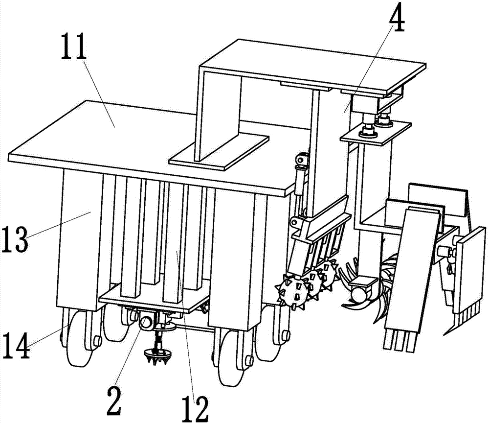
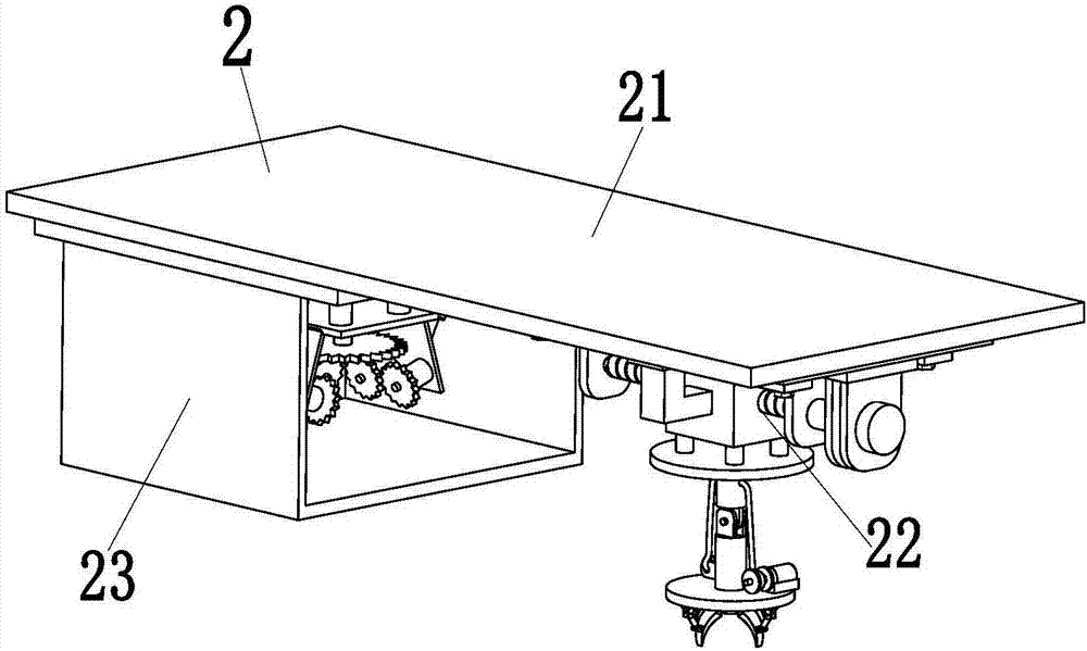
[0025] Such as Figure 1 to Figure 11 As shown, a track damping stone pusher with impurity removal function includes a base plate 11, two rows of support columns 12 are symmetrically arranged in the middle of the lower end of the base plate 11, and track removal of impurities is installed at the lower ends of the two rows of support columns 12. In the device 2, two rows of support columns 12 play the role of stably supporting the track removal device 2, and the track removal device 2 can realize the automatic removal function in the middle of the rail; the lower end of the base plate 11 is symmetrically provided with four legs 13, and The lower end of each leg 13 is provided with a universal wheel 14, and the present invention can be moved to a ...


PUM


Abstract

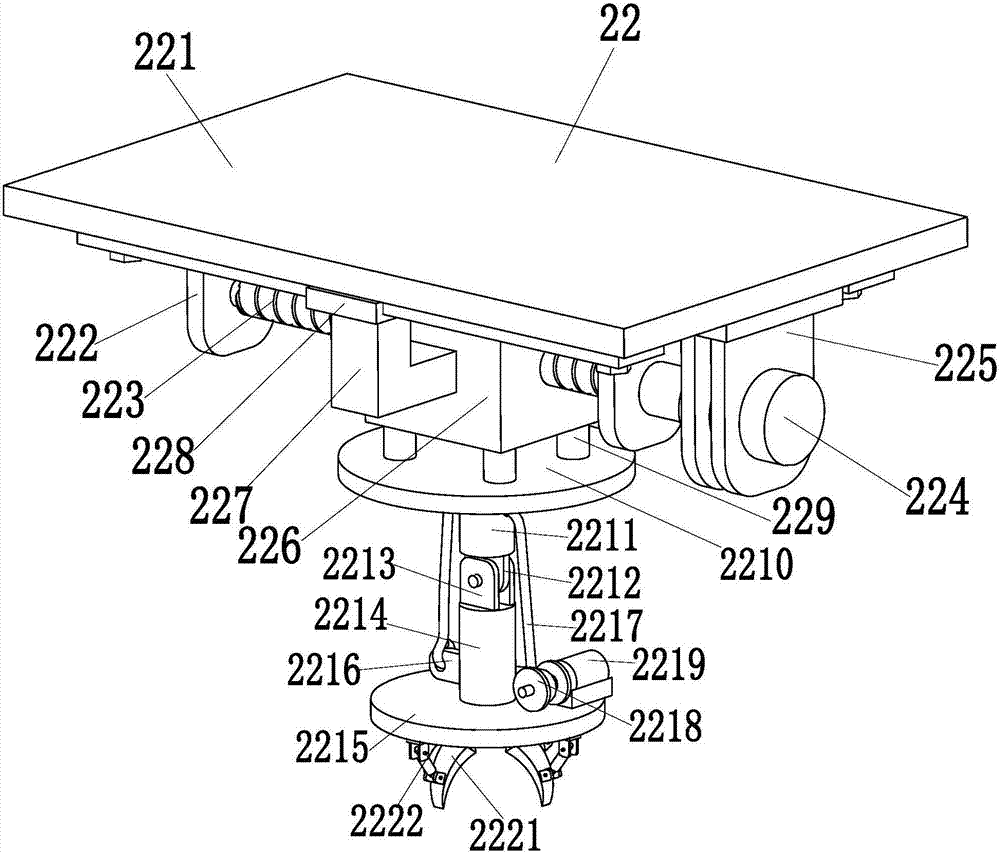
The invention relates to a track damping stone extruding and pushing machine with a debris removal function. The track damping stone extruding and pushing machine comprises a base plate; two rows of supporting columns are symmetrically arranged at the middle part at the lower end of the base plate; a track debris removal device is mounted at the lower ends of the two rows of supporting columns; the track debris removal device can realize the automatic debris removal function between rails; four supporting legs are symmetrically arranged at the lower end of the base plate, and a universal wheel is arranged at the lower end of each supporting leg; a track stone extruding and pushing device is mounted on the right side at the upper end surface of the base plate, and the track stone extruding and pushing device can realize the automatic extruding and pushing function of track damping stones; the track debris removal device comprises a debris removal supporting plate welded to the lower end surfaces of the two rows of supporting columns; a gripping and conveying mechanism is mounted on the right side at the lower end surface of the debris removal supporting plate; the gripping and conveying mechanism can realize the automatic gripping and conveying function to debris between the rails; and an adjustable crushing mechanism is mounted on the left side at the lower end surface of the debris removal supporting plate. Through the adoption of the track damping stone extruding and pushing machine disclosed by the invention, an automatic maintenance function integrating stone extruding and pushing as well as debris removal of the rails can be realized.

Description

technical field [0001] The invention relates to the technical field of rails, in particular to a rail vibration-damping stone pusher with the function of removing impurities. Background technique [0002] With the continuous development of rail technology in China, rails are mainly divided into high-speed rails, bullet train rails, train rails, and subway rails. Due to the increasing number of rails, the number of rail maintenance workers is also increasing. The existing rail maintenance mainly It is divided into checking the rail device, trimming the protective trees on both sides of the rail, pushing the damping stones on both sides of the rail, and removing impurities in the middle of the rail, etc., but the existing rail maintenance methods have the following defects: 1. Because high-speed rail, bullet trains, trains, and subways There will be a lot of vibration when moving up. In order to reduce the vibration, a large number of stones are usually laid on both sides of t...

Claims


Application Information

Patent Timeline
Patent Type & Authority Patents(China)
IPC IPC(8): E01B19/00E01H8/00
CPCE01B19/00E01H8/00
Inventor 庄巍
Owner 湖州优研知识产权服务有限公司
Learn More