
Target searching method and apparatus

A target and target object technology, applied in the field of automatic control of drones, can solve problems such as the inability to directly lock the target, the difficulty of drones, and the restriction of GPS signals

Inactive Publication Date: 2017-02-01
四川天辰智创科技有限公司
View PDF10 Cites 7 Cited by
  • Summary
  • Abstract
  • Description
  • Claims
  • Application Information

AI Technical Summary

Problems solved by technology

[0003] However, in the existing technology, the position information of the UAV is mainly corrected by GPS, which cannot directly lock the target. It needs to rely on third-party technology to lock the target object, and then correct its own position to approach the target, especially when the target When it is a moving object, it is more difficult for the UAV to lock the target, and the process of target locking is also subject to the strength of the GPS signal

Method used


Image

  • Target searching method and apparatus
  • Target searching method and apparatus
  • Target searching method and apparatus

Examples


no. 1 example

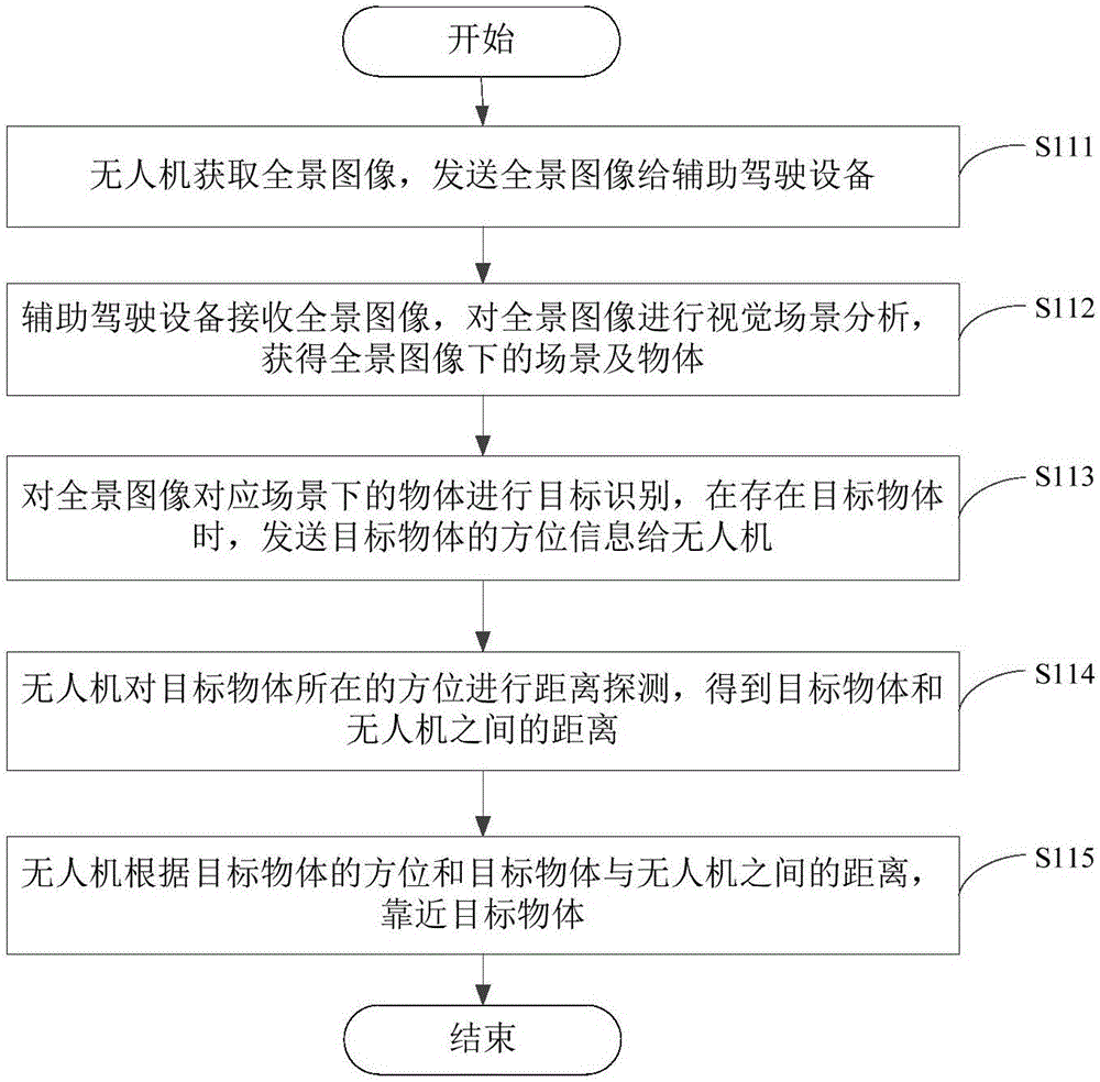
[0059] Please refer to image 3 , image 3 It is a flow chart of the method for finding a target provided by the first embodiment of the present invention, and the method is applied to the UAV 100 and the auxiliary driving device 200 connected by communication. The specific process of the method for finding the target will be described in detail below.

[0060] Step S111 , the UAV 100 acquires a panoramic image, and sends the panoramic image to the driving assistance device 200 .

[0061] In this embodiment, the UAV 100 can collect panoramic images around the UAV 100 by setting two panoramic optical cameras. Specifically, the installation positions of the two panoramic optical cameras may be opposite, so as to realize image collection without dead angles. In this embodiment, preferably, one of the panoramic optical cameras is arranged on one side of the propeller of the UAV 100 for acquiring images of the sky, and the other panoramic optical camera is arranged on the abdome...

no. 2 example

[0075] Please refer to Figure 4 , Figure 4 It is a flow chart of the method for finding a target provided by the second embodiment of the present invention, and the method is applied to the auxiliary driving device 200 connected in communication with the UAV 100 . The specific process of the method for finding the target will be described in detail below.

[0076] Step S211 , receiving the panoramic image captured by the UAV 100 .

[0077] Specifically, after the UAV 100 obtains the panoramic image through the panoramic optical camera, it transmits the data of the panoramic image to the driving assistance device 200 .

[0078] Step S212, performing visual scene analysis on the panoramic image to obtain scenes and objects under the panoramic image.

[0079] In this embodiment, the driving assistance device 200 uses a neural network algorithm of deep learning to perform visual scene analysis on the panoramic image to obtain scenes and objects under the panoramic image.

[...

no. 3 example

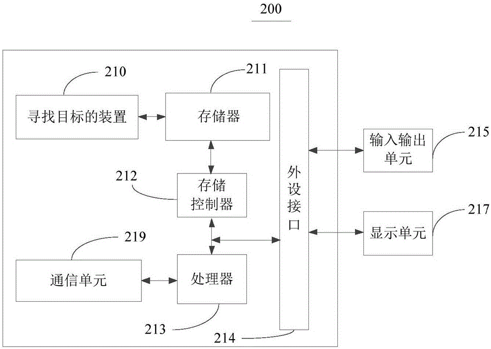
[0087] Please refer to Figure 5 , Figure 5 The third embodiment of the present invention provides a device 210 for finding a target, and the device 210 is applied to a driving assistance device 200 connected in communication with the UAV 100 . The device 210 includes: a receiving module 2101 , a visual scene analysis module 2102 , and a target recognition module 2103 .

[0088] The receiving module 2101 is configured to receive the panoramic image captured by the UAV 100 .

[0089] The receiving module 2101 is configured to execute step S2111 in the second embodiment.

[0090] The visual scene analysis module 2102 is configured to perform visual scene analysis on the panoramic image to obtain scenes and objects under the panoramic image. The visual scene analysis module 2102 uses a neural network algorithm based on deep learning to analyze the received panoramic image to obtain scenes and objects under the panoramic image.

[0091] The visual scene analysis module 2102 i...


PUM


Abstract

The invention provides a target searching method and apparatus. The target searching method comprises the following steps: an unmanned aerial vehicle obtaining a panoramic image and sending the panoramic image to an auxiliary driving device; the auxiliary driving device receiving the panoramic image and performing visual scene analysis on the panoramic image so as to obtain a scene and objects in the panoramic image; performing target identification on the objects in the scene corresponding to the panoramic image, and in the presence of a target object, sending orientation information of the target object to the unmanned aerial vehicle; the unmanned aerial vehicle performing distance detection on orientation of the target object to obtain a distance between the target object and the unmanned aerial vehicle; and the unmanned aerial vehicle, according to the orientation of the target object and the distance between the target object and the unmanned aerial vehicle, approaching the target object. The method solves the problem of difficulty in locking the target object and even losing the target object due to incapability of obtaining the position of the target object in real time by the unmanned aerial vehicle when the target object moves. The method has the advantage of continuously locking the target object.

Description

technical field [0001] The invention relates to the field of automatic control of unmanned aerial vehicles, in particular, to a method and device for using unmanned aerial vehicles to find targets. Background technique [0002] Drones have been a very active area of ​​research in recent years. Through radar, remote control or communication devices and other equipment, the UAV can be tracked, remotely controlled or digitally transmitted. Small UAVs can also take off, land and hover vertically in tight spaces, making them ideal platforms for reconnaissance, surveillance, tracking and other tasks. In the civilian field, people can use the camera equipment carried by it to take pictures, and can also take high-altitude aerial photography. And it can complete special tasks by sending drones to areas where manpower is inconvenient. The future of drones is extremely broad. [0003] However, in the existing technology, the position information of the UAV is mainly corrected by G...

Claims


Application Information

Patent Timeline
Patent Type & Authority Applications(China)
IPC IPC(8): G05D1/12
CPCG05D1/12
Inventor 滕龙孙晓刚李泽塬任骥张弟
Owner 四川天辰智创科技有限公司
Learn More