Three-dimensional base isolation support capable of presetting vertical early rigidity
A shock-isolation support and vertical shock-isolation technology, applied in the direction of shock-proof, building components, building types, etc., can solve the problems of reducing the cost of shock-isolation, shortening the effective working length of the spring, not being able to stretch, energy-consuming and shock-absorbing, etc., to achieve The effect of buffering tensile and compressive shocks, reducing the cost of wind and shock resistance, and reducing the risk of overturning
- Summary
- Abstract
- Description
- Claims
- Application Information
AI Technical Summary
Problems solved by technology
Method used
Image
Examples
example 1
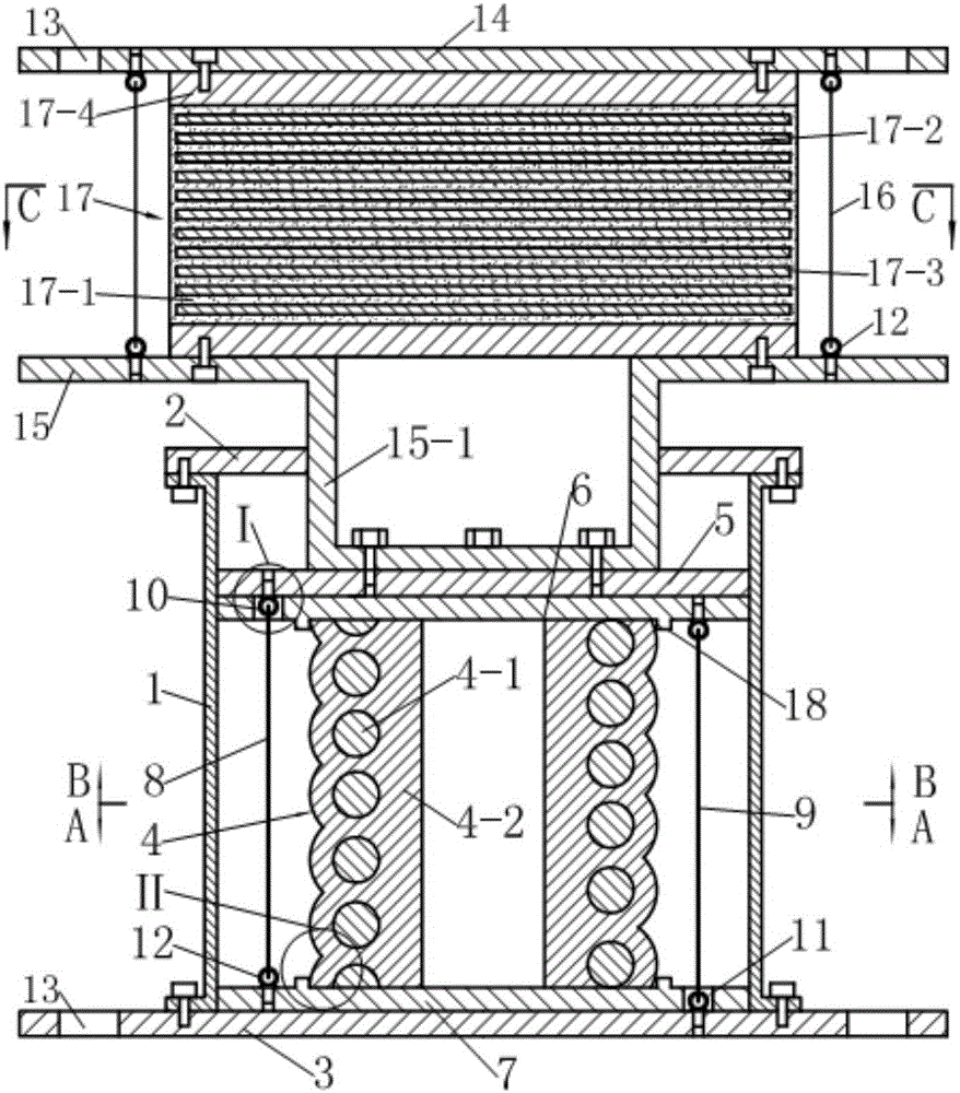
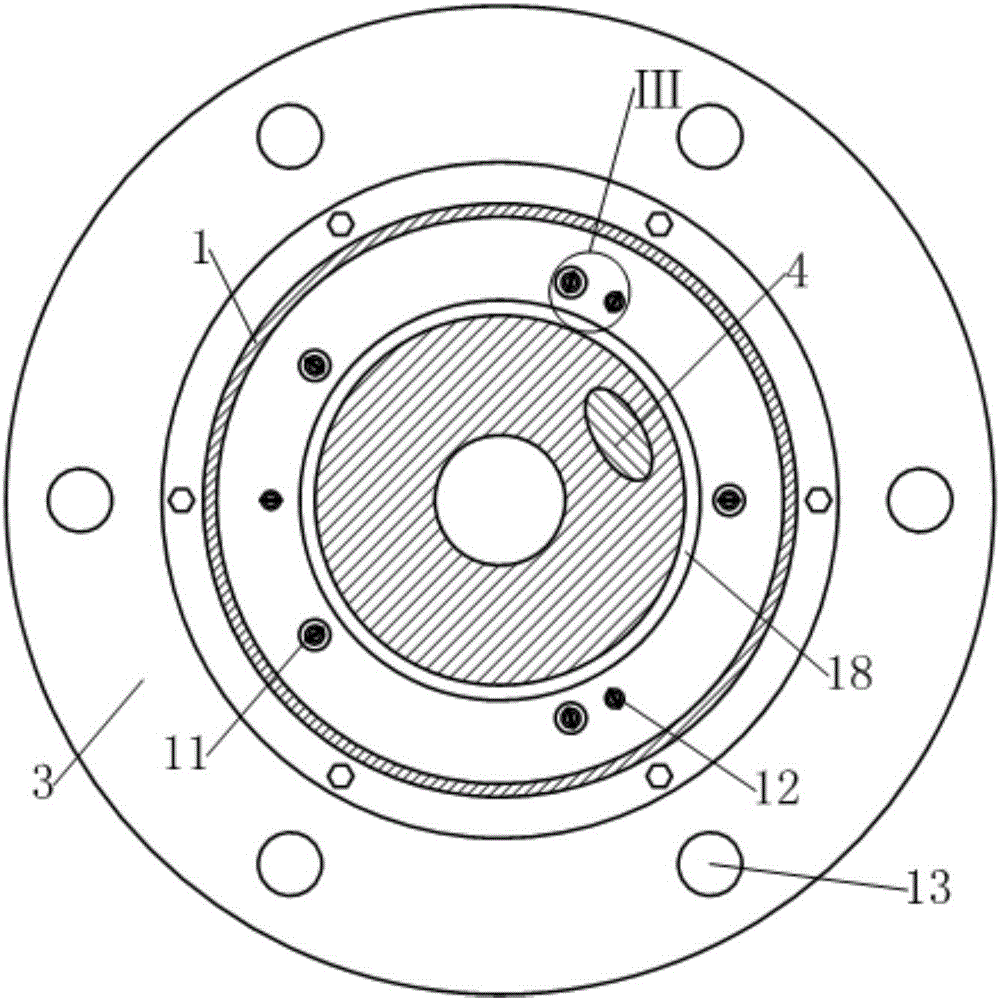
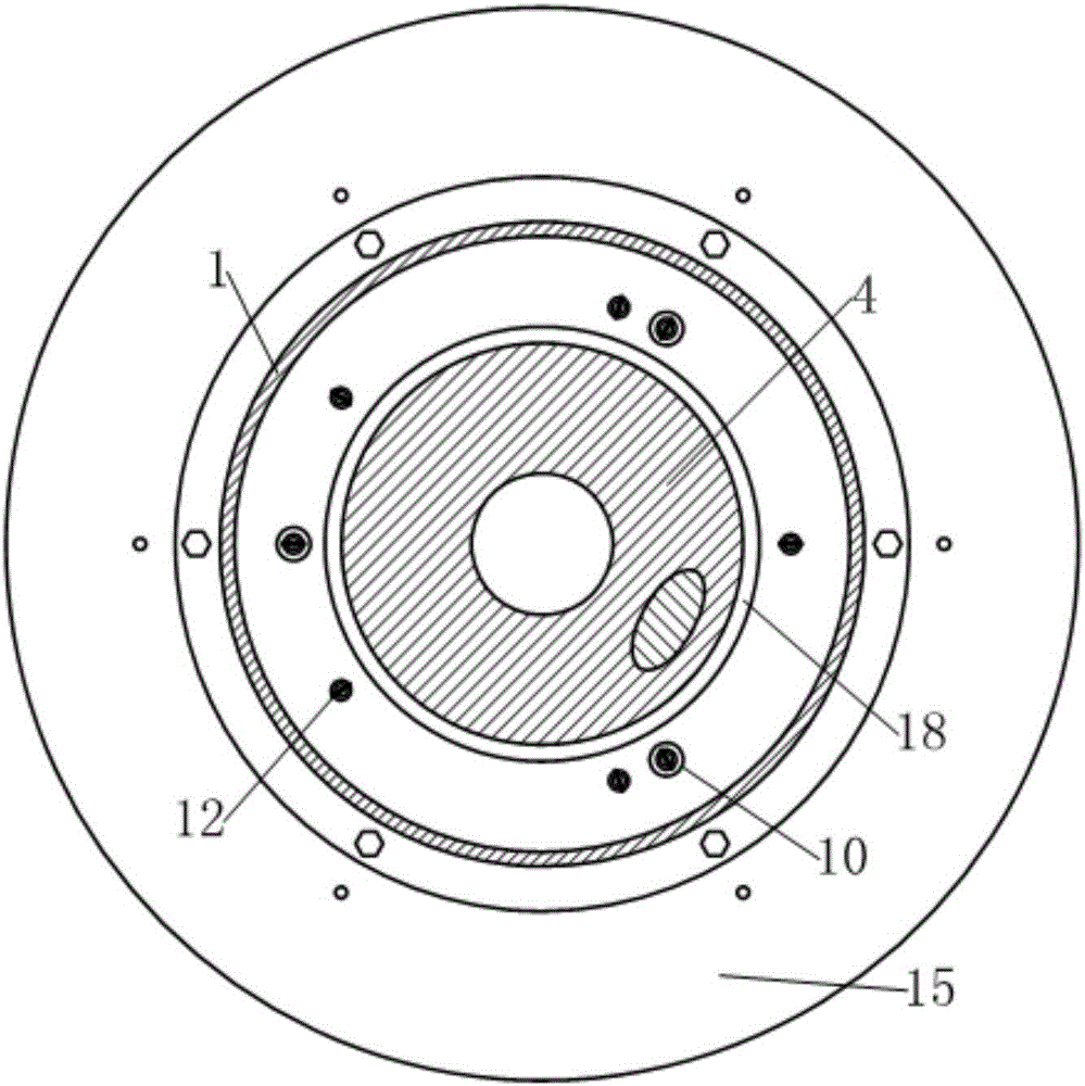
[0042] see figure 1 , the three-dimensional seismic isolation bearing in this example is composed of laminated rubber isolation bearings and vertical isolation bearings connected in series up and down.
[0043] see figure 1 and Figure 4 , the laminated rubber shock-isolation bearing includes an upper connecting plate 14, a lower connecting plate 15, a laminated rubber pad 17 clamped between the upper and lower connecting plates and six tensile steel cables 16; wherein, the upper Both the connecting plate 14 and the lower connecting plate 15 are disc-shaped, and the edge of the upper connecting plate 14 is provided with mounting holes 13; the main body of the laminated rubber pad 17 is alternately composed of a layer of rubber 17-1 and a layer of steel plate 17-2 After lamination, it is molded and vulcanized, and a rubber protective layer 17-3 is naturally formed around it during the process of molded vulcanization. The upper and lower end surfaces of the main body of the...
example 2
[0056] This example has the following differences from Example 1:
[0057] see Figure 8-10 , the first group of preloaded steel cables 8 and the second group of preloaded steel cables 9 are composed of three preloaded steel cables.
[0058] see Figure 8-10 , the upper head of the first group of preloaded steel cables 8 and the lower head of the second group of preloaded steel cables 9 are respectively fixed on the driving platen 5 and the base by using cable self-locking anchors 19 instead of the eyebolts in Example 1 3; in this example, the middle part of the base 3 needs to be thickened and raised upwards to form an inverted washbasin shape, so as to facilitate the installation of the wire rope self-locking anchor 19.
[0059] see Figures 11 to 13 , and combined with Figure 7, the cable self-locking anchor 19 is composed of a mounting hole provided on the mounting plate 19-1, a jaw 19-2 and a locking bolt 19-4, wherein the mounting plate 19-1 is the drive Pressing p...
example 3
[0063] see Figures 14 to 16 , The difference between this example and Example 2 is that the first group of preloaded steel cables 8 and the second group of preloaded steel cables 9 are composed of five preloaded steel cables.
[0064] Other implementations of this example other than the above are the same as Example 2.
PUM
 Abstract
Description
Claims
Application Information
 - R&D
- Intellectual Property
- Life Sciences
- Materials
- Tech Scout
- Unparalleled Data Quality
- Higher Quality Content
- 60% Fewer Hallucinations
Browse by: Latest US Patents, China's latest patents, Technical Efficacy Thesaurus, Application Domain, Technology Topic, Popular Technical Reports.
© 2025 PatSnap. All rights reserved.Legal|Privacy policy|Modern Slavery Act Transparency Statement|Sitemap|About US| Contact US: help@patsnap.com


