
Rotary knob type drive-by-wire gear shifter

A shift-by-wire, knob-type technology, applied in the control device, transmission control, components with teeth, etc., can solve the problems of occupying a large cockpit space, affecting the appearance, reducing driving comfort, etc. Conducive to the effect of light weight and weight reduction

Inactive Publication Date: 2017-02-08
NANJING AOLIAN AUTOMOTIVE ELECTRONICS TECH CO LTD
View PDF11 Cites 26 Cited by
  • Summary
  • Abstract
  • Description
  • Claims
  • Application Information

AI Technical Summary

Problems solved by technology

[0003] The traditional electronic shifter mostly adopts the structure of the shift rod. The layout and design of the shifter, the shape, layout and structural design of the shift handle are very complicated, and it takes up a lot of space in the cockpit, which affects the appearance and reduces the driving force. comfort

Method used


Image

  • Rotary knob type drive-by-wire gear shifter
  • Rotary knob type drive-by-wire gear shifter
  • Rotary knob type drive-by-wire gear shifter

Examples


Embodiment Construction

[0031] The present invention will be further elaborated below in conjunction with specific drawings and specific embodiments. The present invention can also have other embodiments. All equivalent substitutions or equivalent transformations formed by those skilled in the art without departing from the principles of the present invention through changes and modifications all fall within the scope of protection required by the present invention.

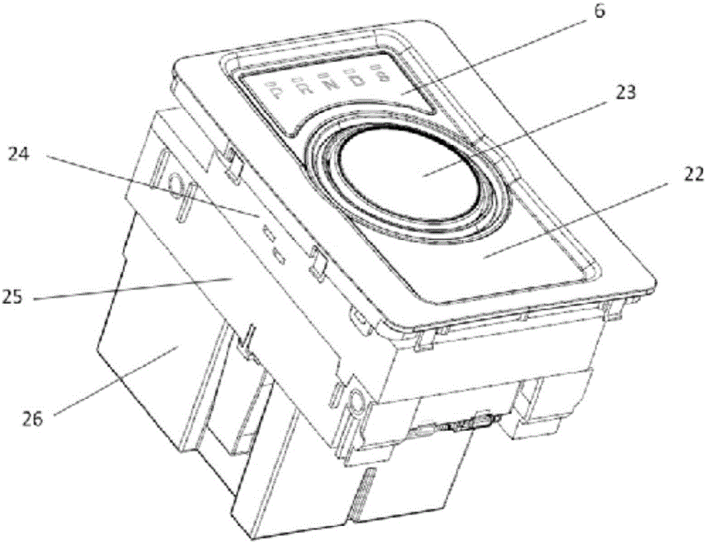
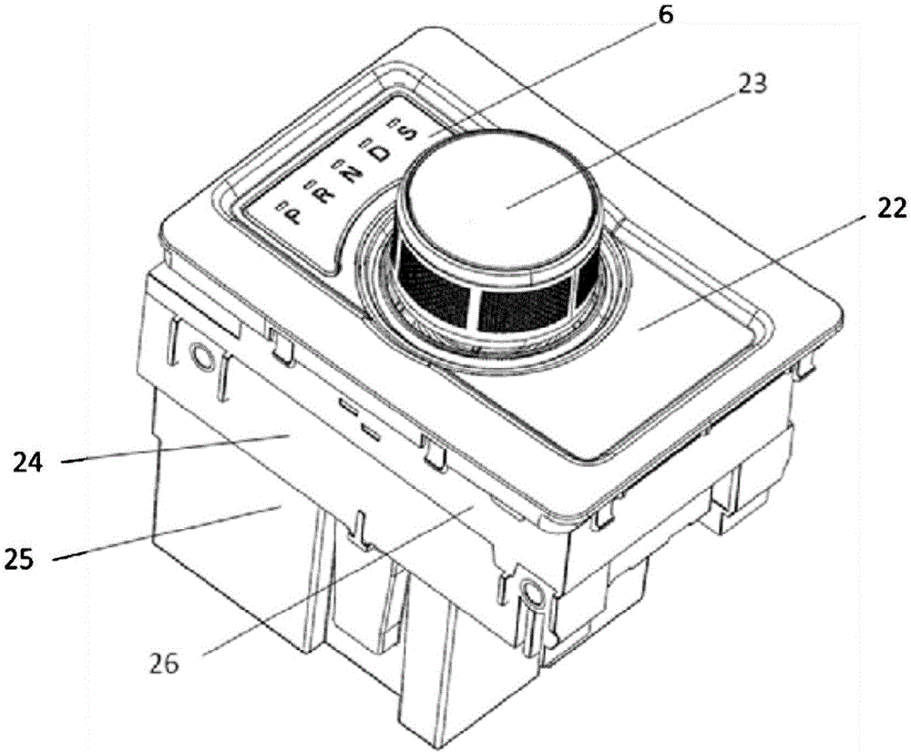
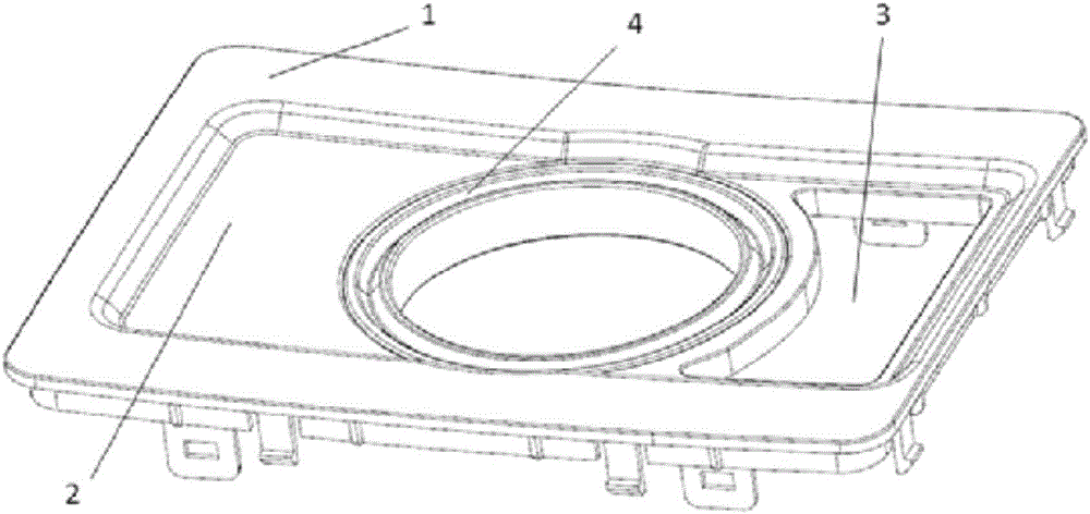
[0032] refer to figure 1 It is the overall appearance diagram of the knob-by-wire shifter of the present invention (the shift knob is in the descending position), refer to figure 2 The external view of the knob-type shifter by wire of the specific example of the present invention (the shift knob is in the rising position), refer to image 3 For a panel view of the knob-by-wire shifter, refer to Figure 4 It is the upper side view of the upper housing and the light board of the knob-type shifter by wire, refer to Figure 5 It is the...


PUM


Abstract

The invention provides a rotary knob type drive-by-wire gear shifter and relates to the technical field of electronic and electric control of automobiles. The rotary knob type drive-by-wire gear shifter comprises an upper shell, a middle shell, a lower shell, a gear shifting rotary knob and two linear Hall sensors, wherein the upper shell, the middle shell and the lower shell are fixedly connected together; the gear shifting rotary knob is arranged between the upper shell and the middle shell in a penetration manner; the two linear Hall sensors are arranged below the gear shifting rotary knob and are simultaneously used for sensing a request gear of a gear lever. The rotary knob type drive-by-wire gear shifter provided by the invention is capable of improving the driving comfort, saving the internal space of the automobile and also realizing lightening of the overall automobile.

Description

technical field [0001] The invention relates to the technical field of automotive electronic control, in particular to a knob-type wire-controlled shifter. Background technique [0002] With the rapid development of automotive electronics, modern vehicles increasingly use electronic shifters to communicate with transmission controllers. This type of electronic shifter usually senses the driver's selected gear through a shift lever position sensor, and the transmission controller controls the vehicle's gearbox to shift gears based on these inputs. The vehicle controller is usually connected to other vehicle sensors to prevent the driver from unsafe shifting operations, such as when the driver shifts from D to R while the car is running at high speed. To further prevent the electronic shifter from causing the transmission to perform unsafe shift operations, solenoid valves or other actuators are added to the electronic shifter to prevent the shift lever from going into an uns...

Claims


Application Information

Patent Timeline
IPC IPC(8): F16H59/12B60K20/02
CPCF16H59/12B60K20/02
Inventor 李琼徐波王强
Owner NANJING AOLIAN AUTOMOTIVE ELECTRONICS TECH CO LTD
Learn More