
A spinning type manual hydraulic steel bar cutting device that can work in both directions

A bidirectional working and cutting device technology, applied in the field of steel cutting equipment, can solve the problems of slow cutting speed, complicated adjustment, low efficiency, etc., and achieve the effect of wide application range and speeding up cutting speed.

Inactive Publication Date: 2017-12-22
盐城市双强管桩有限公司
View PDF7 Cites 0 Cited by
  • Summary
  • Abstract
  • Description
  • Claims
  • Application Information

AI Technical Summary

Problems solved by technology

The adjustment of the above-mentioned patents is complicated, and because the steel bar can only be cut on one side, the cutting speed is slow and the efficiency is low

Method used


Image

  • A spinning type manual hydraulic steel bar cutting device that can work in both directions
  • A spinning type manual hydraulic steel bar cutting device that can work in both directions
  • A spinning type manual hydraulic steel bar cutting device that can work in both directions

Examples


Embodiment Construction

[0016] The present invention will be further described below in conjunction with accompanying drawing:

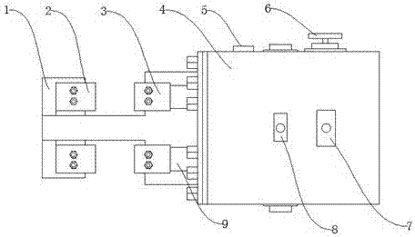
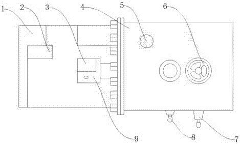
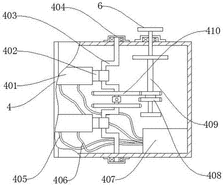
[0017] Such as Figure 1-Figure 3 As shown, a spinning type manual hydraulic steel bar cutting device that can work in both directions includes a knife seat 1 and a control box 4. A fixed knife 2 is installed on the knife seat 1, and a moving knife 3 is installed next to the fixed knife 2. , the moving knife 3 is used to cut steel bars, the control box 4 is arranged next to the knife seat 1, and the front end of the control box 4 is provided with a hydraulic rod 9, and the hydraulic rod 9 is used to control the moving knife 3 , the control box 4 is provided with an oil discharge valve 5, and a hand wheel 6 is provided beside the oil discharge valve 5, and the hand wheel 6 is used to load hydraulic oil, and a reversing rod 7 is provided on the side of the control box 4 , the reversing rod 7 is used to switch the use of the fixed knife 2, and a linkage rod 8 is arranged besi...


PUM


Abstract

The invention discloses a spinning type manually-operated hydraulic steel bar cutting-off device capable of working in two directions. The device comprises a knife seat and a control cabinet. Stationary knives are mounted on the knife seat. A movable knife is mounted beside each stationary knife. The control cabinet is arranged beside the knife seat. Hydraulic rods are arranged at the front end of the control cabinet. Oil drain valves are arranged above the control cabinet. A hand wheel is arranged beside the oil drain valves. A reversing rod is arranged on the side face of the control cabinet. A linkage rod is arranged beside the reversing rod. The spinning type manually-operated hydraulic steel bar cutting-off device has the beneficial effects that the two-directional cutting-off knives can be used separately or together; the application scope is wide; and in addition, steel bar cutting-off speed can be increased.

Description

technical field [0001] The invention relates to the field of steel material cutting equipment, in particular to a spinning type manual hydraulic steel bar cutting device capable of bidirectional work. Background technique [0002] Steel bars are widely used in construction. It can be used as prefabricated components, reinforced concrete and stirrups, etc. For this reason, it is necessary to cut the steel bars. The steel bar cutting machine is a tool for cutting steel bars. The Chinese patent application number is 201210507085.3, the specific content is: a steel bar cutting machine is disclosed, including a base, a discharge rack is provided on one side of the base, the discharge rack is connected to the feeding chute, an adjustment block is provided at one end of the base, and an adjustment pad is provided at the other end. A length-setting mechanism is provided, and a matching fixed knife and a moving knife are arranged in the middle. The said length-setting mechanism inclu...

Claims


Application Information

Patent Timeline
Patent Type & Authority Patents(China)
IPC IPC(8): B21F11/00
CPCB21F11/00
Inventor 李光明凌德祥邵淑敏凌慧
Owner 盐城市双强管桩有限公司
Learn More