A wire harness cutting device for instrument production

A technology for cutting equipment and wire harnesses, which is applied in the field of wire harness cutting equipment for instrument production, which can solve the problems of uneven cutting and slow speed, and achieve the effects of fast cutting speed, convenient use, and uniform cutting

Active Publication Date: 2020-04-03
常州中端电器有限公司
View PDF7 Cites 0 Cited by
  • Summary
  • Abstract
  • Description
  • Claims
  • Application Information

AI Technical Summary

Problems solved by technology

[0005] In order to overcome the shortcomings of slow speed and uneven cutting when cutting the wire harness manually, the technical problem of the present invention is to provide a wire harness cutting device for instrument production with fast cutting speed and relatively uniform cutting

Method used


Image

  • A wire harness cutting device for instrument production
  • A wire harness cutting device for instrument production
  • A wire harness cutting device for instrument production

Examples


Embodiment 1

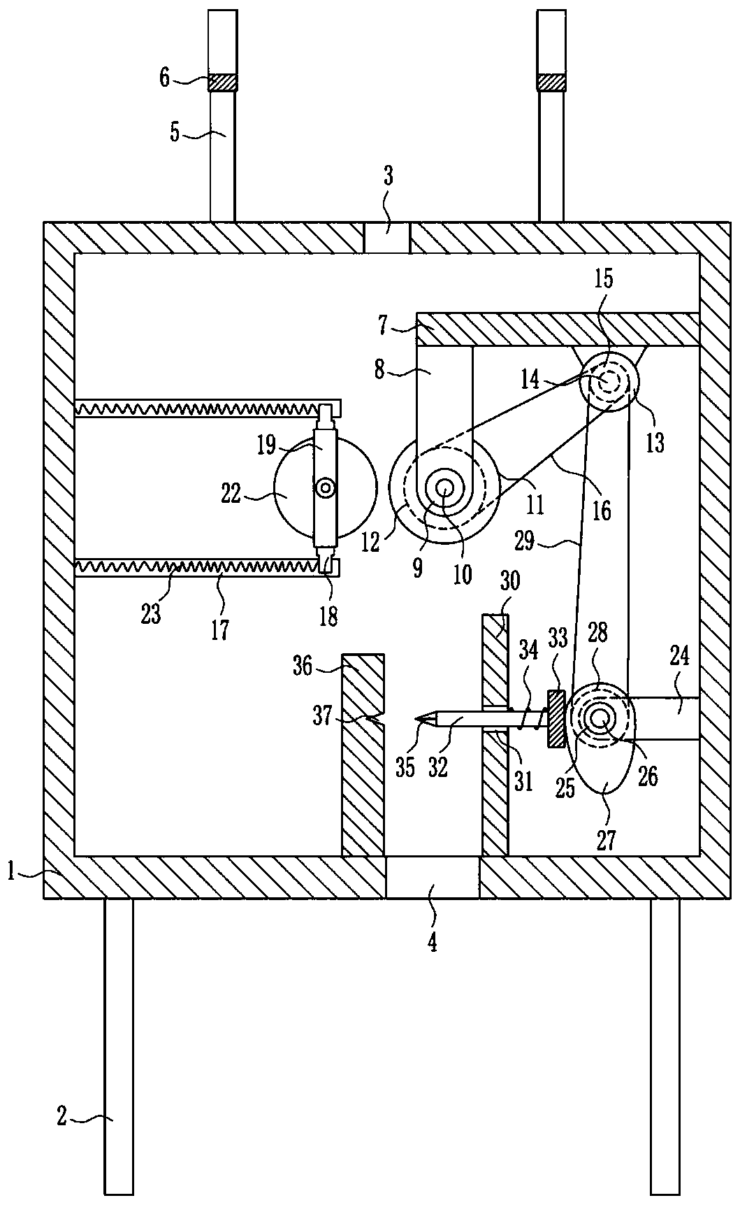
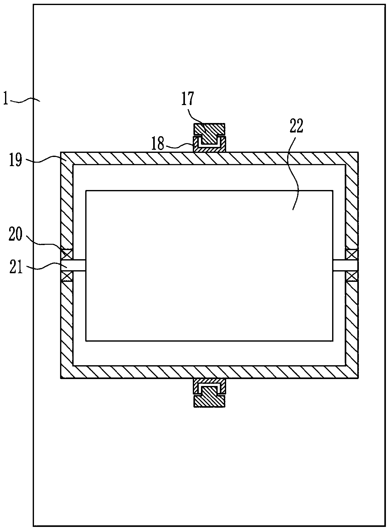
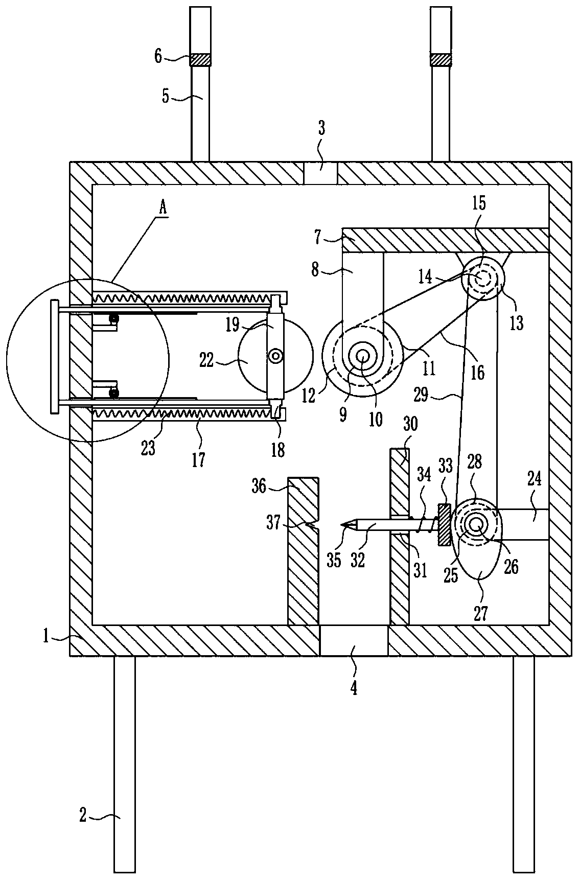
[0023] A wire harness cutting device for instrument production, such as Figure 1-5As shown, it includes a box body 1, a leg 2, a support plate 5, an arc plate 6, a first horizontal plate 7, a first vertical plate 8, a first bearing seat 9, a first rotating shaft 10, a first roller 11, First pulley 12, first motor 13, second rotating shaft 14, double groove pulley 15, first flat belt 16, first slide rail 17, first slider 18, frame 19, third bearing seat 20, third rotating shaft 21. The second roller 22, the first spring 23, the second horizontal plate 24, the fourth bearing seat 25, the fourth rotating shaft 26, the cam 27, the second pulley 28, the second flat belt 29, the second vertical plate 30, the first A guide rod 32, a contact plate 33, a second spring 34, a cutter 35 and a third vertical plate 36, legs 2 are installed at the four corners of the bottom of the box body 1, and a feed inlet 3 is arranged in the middle of the top of the box body 1. There is a feeding open...

Embodiment 2

[0025] A wire harness cutting device for instrument production, such as Figure 1-5 As shown, it includes a box body 1, a leg 2, a support plate 5, an arc plate 6, a first horizontal plate 7, a first vertical plate 8, a first bearing seat 9, a first rotating shaft 10, a first roller 11, First pulley 12, first motor 13, second rotating shaft 14, double groove pulley 15, first flat belt 16, first slide rail 17, first slider 18, frame 19, third bearing seat 20, third rotating shaft 21. The second roller 22, the first spring 23, the second horizontal plate 24, the fourth bearing seat 25, the fourth rotating shaft 26, the cam 27, the second pulley 28, the second flat belt 29, the second vertical plate 30, the first A guide rod 32, a contact plate 33, a second spring 34, a cutter 35 and a third vertical plate 36, legs 2 are installed at the four corners of the bottom of the box body 1, and a feed inlet 3 is arranged in the middle of the top of the box body 1. There is a feeding ope...

Embodiment 3

[0028] A wire harness cutting device for instrument production, such as Figure 1-5 As shown, it includes a box body 1, a leg 2, a support plate 5, an arc plate 6, a first horizontal plate 7, a first vertical plate 8, a first bearing seat 9, a first rotating shaft 10, a first roller 11, First pulley 12, first motor 13, second rotating shaft 14, double groove pulley 15, first flat belt 16, first slide rail 17, first slider 18, frame 19, third bearing seat 20, third rotating shaft 21. The second roller 22, the first spring 23, the second horizontal plate 24, the fourth bearing seat 25, the fourth rotating shaft 26, the cam 27, the second pulley 28, the second flat belt 29, the second vertical plate 30, the first A guide rod 32, a contact plate 33, a second spring 34, a cutter 35 and a third vertical plate 36, legs 2 are installed at the four corners of the bottom of the box body 1, and a feed inlet 3 is arranged in the middle of the top of the box body 1. There is a feeding ope...


PUM


Abstract

The invention relates to cutting-off equipment, in particular to wire hardness cutting-off equipment for instrument production. According to the technical aims, the wire hardness cutting-off equipmentfor instrument production is high in cutting-off speed and uniform in cutting-off. The wire hardness cutting-off equipment for instrument production comprises a tank, supporting legs, supporting boards, arc-shaped boards, a first transverse board, a first vertical board, a first bearing pedestal, a first rotary shaft, a first roller, a first belt wheel and the like. The supporting legs are installed at four corners of the bottom of the tank; a feeding inlet is formed in the middle of the top of the tank; a discharging outlet is formed in the middle of the bottom of the tank; the two supporting boards are installed on the top of the exterior of the tank; and the feeding inlet is located between the two supporting boards. A first motor is used as a driver to drive the first roller to rotate, so that wire harnesses are driven to move downwards; and a cam drives a cutter to cut off the wire harnesses, a movable plate and a fourth spring are also arranged, so that the cut-off wire harnesses are not stacked, and the effects that the wire harnesses are cut off fast and uniformly are achieved accordingly.

Description

technical field [0001] The invention relates to a cutting device, in particular to a wire harness cutting device for instrument production. Background technique [0002] Instrumentation is an instrument or device used to detect, measure, observe, and calculate various physical quantities, material components, and physical parameters. Vacuum leak detectors, pressure gauges, length measuring instruments, microscopes, multipliers, etc. are all instruments. [0003] In a broad sense, instruments and meters can also have functions such as automatic control, alarm, signal transmission and data processing, such as pneumatic regulating instruments and electric regulating instruments used in the automatic control of industrial production processes, as well as distributed instrument control systems. instrumentation. [0004] In the process of instrument production, it is necessary to cut the wire harness. The speed of manual cutting of the wire harness is slow and the cutting is not...

Claims


Application Information

Patent Timeline
Patent Type & Authority Patents(China)
IPC IPC(8): B21F11/00B21F23/00
CPCB21F11/00B21F23/00
Inventor 余明强袁月玲白毅楠
Owner 常州中端电器有限公司
Why Eureka
Try Eureka